
Tubular core assemblies for rolls of paper or other sheet material

Inactive Publication Date: 2001-02-27
KEWIN DANIEL
View PDF11 Cites 13 Cited by
  • Summary
  • Abstract
  • Description
  • Claims
  • Application Information

AI Technical Summary

Benefits of technology

The present invention is based on the discovery that the problem mentioned above is substantially reduced if each plastic annular end member has at least two radially projecting lugs adjacent an end thereof positioned so as to be rotatably balanced, i.e. equi-angularly spaced around the end member, and also has an inner annular surface at said end which is continuous and of constant radius around the circumference thereof, thereby maximizing the cylindrical hoop strength of the annular end member.

Problems solved by technology

When such automated equipment is used, chucks without keys are moved under axial pressure into engagement with the ends of a tubular core assembly, because it is difficult to mount a paper roll on chucks with keys with such automated equipment.
It has been found that, when tubular core assemblies with end members as described above are subjected to such very high continuous axial or radial pressure, the transmission of such pressure through the annular end members to the core member may cause the core member to become distorted under continuous static and / or dynamic loads.
Since the core members of heavy paper rolls may be of considerable length, for example about 5 feet or longer, such distortion may cause serious problems with rolls unwinding at high speed during a printing operation, especially if the rolls are slightly out of round.

Method used


Image

  • Tubular core assemblies for rolls of paper or other sheet material
  • Tubular core assemblies for rolls of paper or other sheet material
  • Tubular core assemblies for rolls of paper or other sheet material

Examples


Embodiment Construction

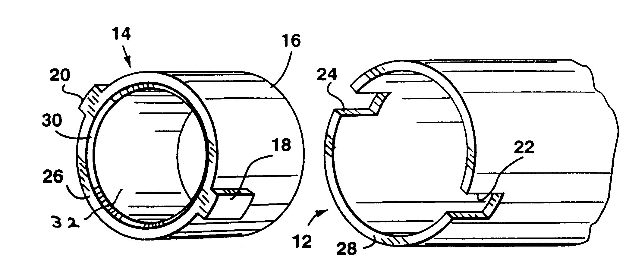
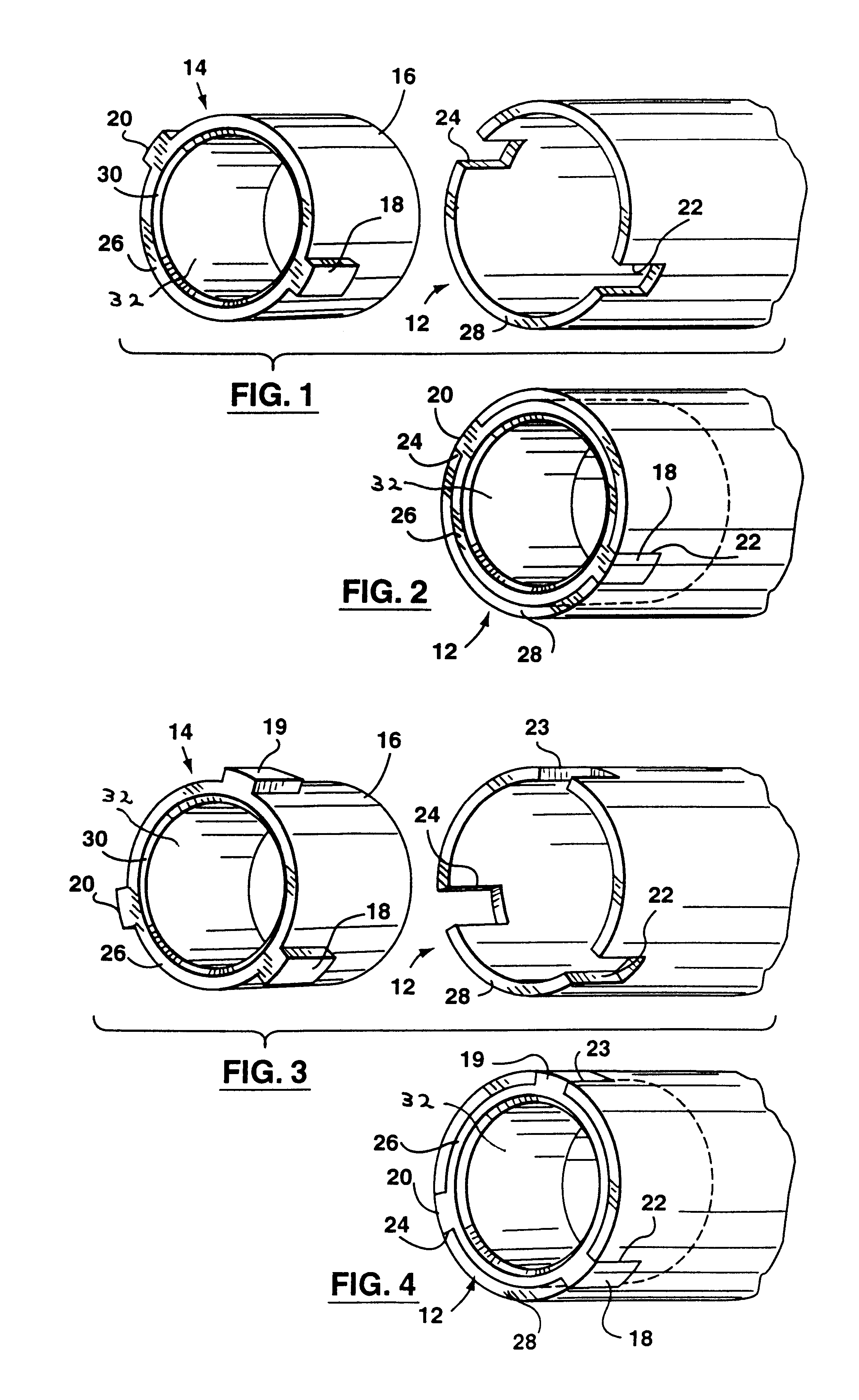
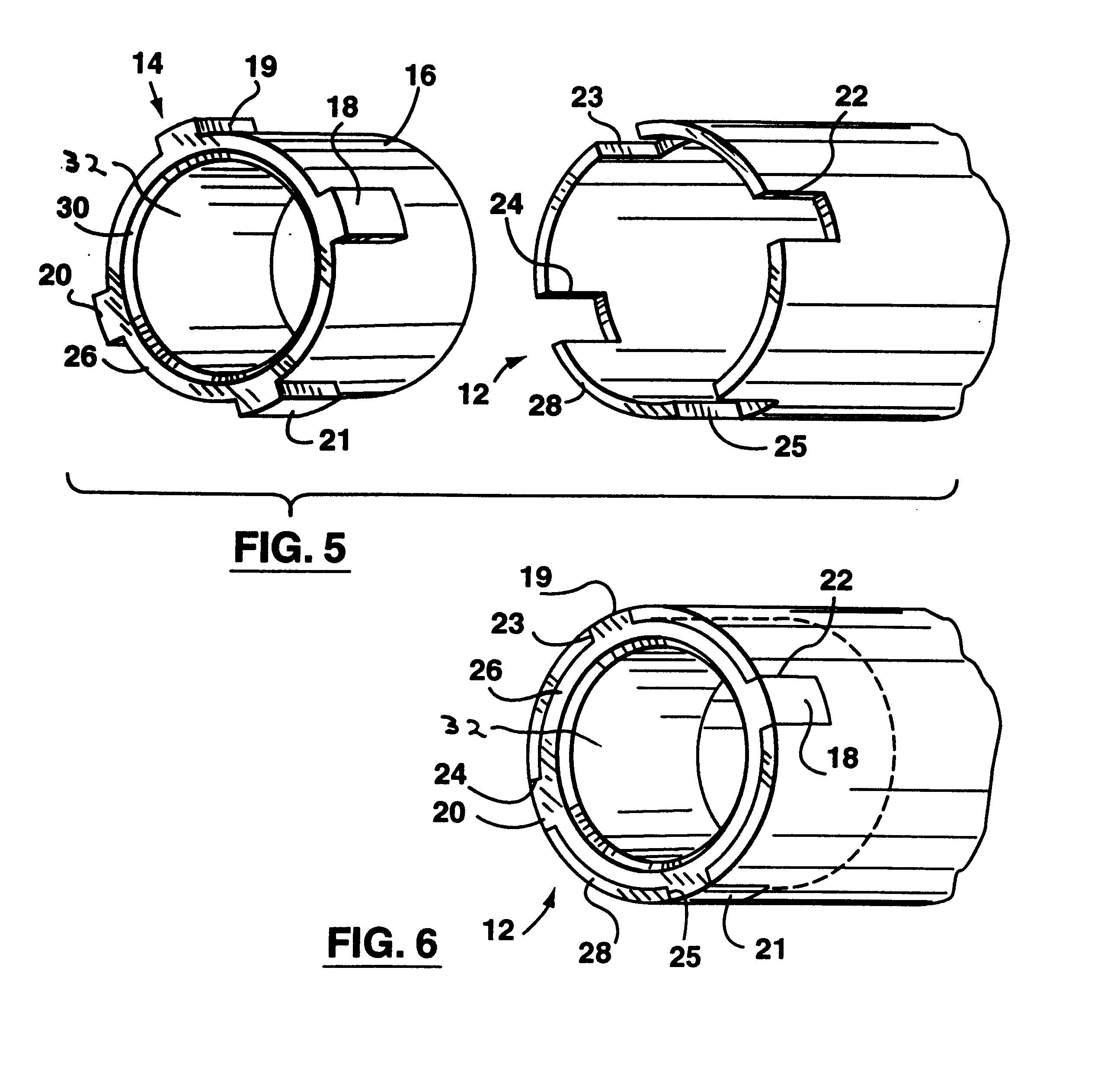
Referring to the drawings, FIGS. 1 and 2 show one end portion of a tubular core assembly for a paper roll which comprises a hollow cylindrical core member 12 of paperboard material, and an annular end member 14 of synthetic plastic material with a sleeve portion 16 within each opposite end portion of the core member 12. The core member 12 has multiple spirally-wound wraps (i.e. laminated plies) of paperboard material, and the synthetic plastic material may be of suitable polymeric material such as injection moulding grade 25% glass filled nylon type 6.

The sleeve portion 16 of each end member 14 has an outer annular surface which is a compression fit, i.e. a friction fit, in a respective end portion of the core member 12. Each end member 14 has a pair of diametrically opposite solid lugs 18, 20 of rectangular section projecting radially outwardly from the end of the sleeve portion 16 at the end of the core member 12. The lugs 18, 20 are located in diametrically opposite notches 22, 2...


PUM


Abstract

A tubular core assembly for roll of paper or other sheet material has a hollow cylindrical core member formed of paperboard material and an annular end member of plastic material within each opposite end portion of the core member. Each end member has an outer annular surface secured to the inner annular surface of the core member and an inner surface shaped to receive a roll supporting chuck. Each end member also has at least two radially-projecting lugs at the respective end of the tubular core assembly positioned so as to be rotationally balanced. The core member has at least two lug-receiving notches at each end receiving lugs of the respective end member to rotationally equalize continuous torque and axial chuck pressure from each end member to the core member. Each end member also has an inner annular surface at the end which is continuous and of constant radius around the circumference thereof.

Description

This invention relates to tubular core assemblies for rolls of paper or other sheet material.Tubular core assemblies which have a hollow cylindrical core member of paper board material and an annular end member of plastic material within each opposite end portion of the core member are known, see for example U.S. Pat. No. 5,236,141 issued Aug. 17, 1993, U.S. Pat. No. 5,595,356 issued Jan. 21, 1997, U.S. Pat. No. 5,615,845 issued Apr. 1, 1997, U.S. Pat. No. 5,725,178 issued Mar. 10, 1998 and U.S. Pat. No. 5,829,713 issued Nov. 3, 1998, the contents of which are hereby incorporated herein by reference.U.S. Pat. No. 5,615,845 and U.S. Pat. No. 5,829,713 mentioned above are particularly concerned with tubular core assemblies intended for mounting on chucks having radially movable portions which are movable radially outwardly to engage the inner surface of a tubular core assembly and on chucks which are movable under axial pressure into engagement with the ends of the tubular core assemb...

Claims


Application Information

Patent Timeline
IPC IPC(8): B65H75/04B65H75/18B65H75/10
CPCB65H75/10B65H75/187B65H2701/31
Inventor KEWIN, DANIEL
Owner KEWIN DANIEL
Learn More