Gun having a rapid fire trigger assembly

a trigger assembly and gun technology, applied in the field of shooting sports equipment, can solve the problems of reducing shooting accuracy, dramatically pulling the gun off the target, and devices which have attempted to solve the foregoing problems,

Inactive Publication Date: 2001-05-01
TRONCOSO VINCENT
View PDF3 Cites 23 Cited by
  • Summary
  • Abstract
  • Description
  • Claims
  • Application Information

AI Technical Summary

Problems solved by technology

When a gunner tries to pull the trigger rapidly and repeatedly, shooting accuracy decreases because of the anxiety of the gunner, because his concentration is focused on the act of repeatedly rapidly pulling the trigger instead of holding his gun aim and also because pulling or squeezing the trigger, especially when done rapidly and repeatedly, inevitably applies an angled torque to the gun through the t

Method used


Image

  • Gun having a rapid fire trigger assembly
  • Gun having a rapid fire trigger assembly
  • Gun having a rapid fire trigger assembly

Examples


Embodiment Construction
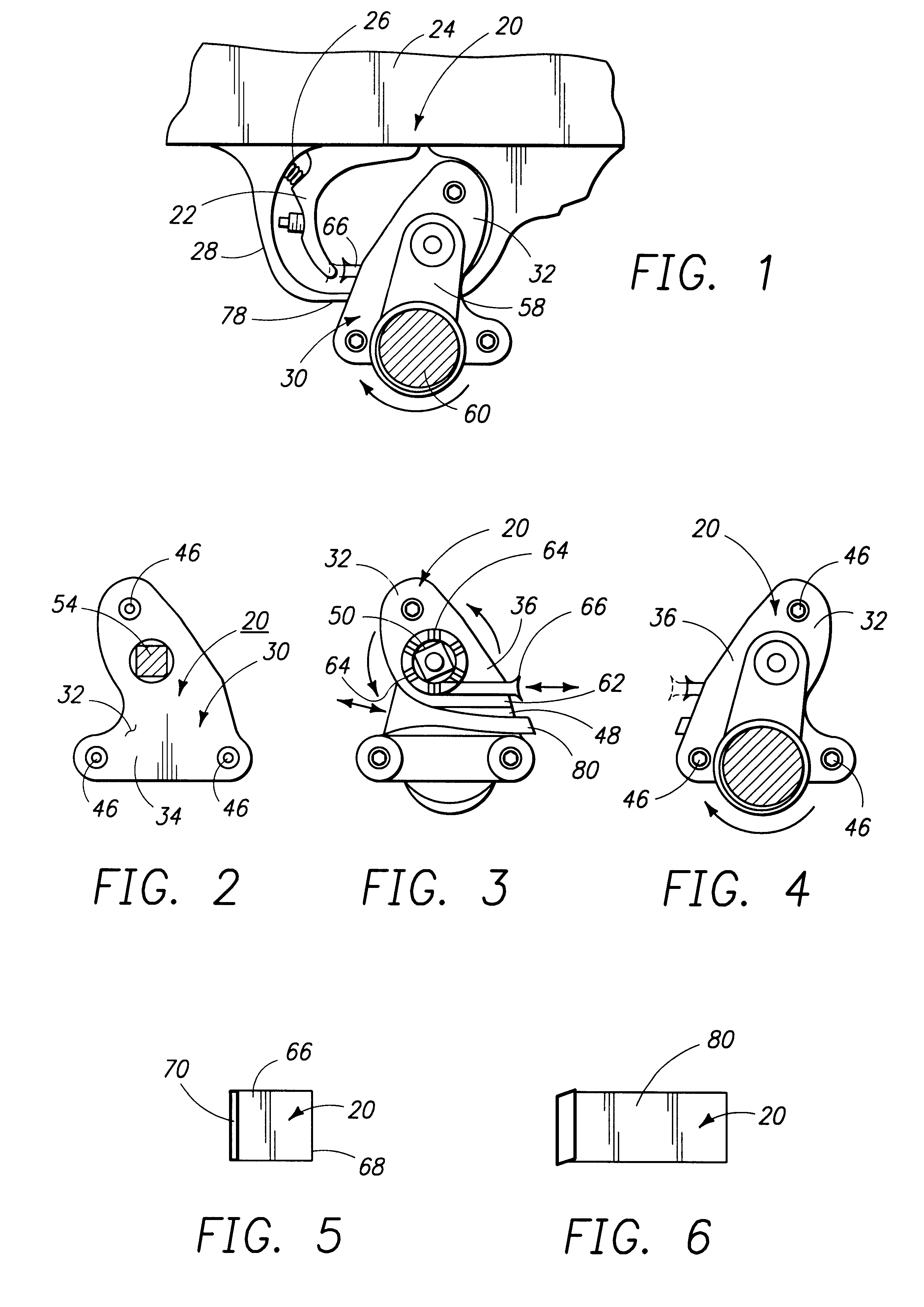
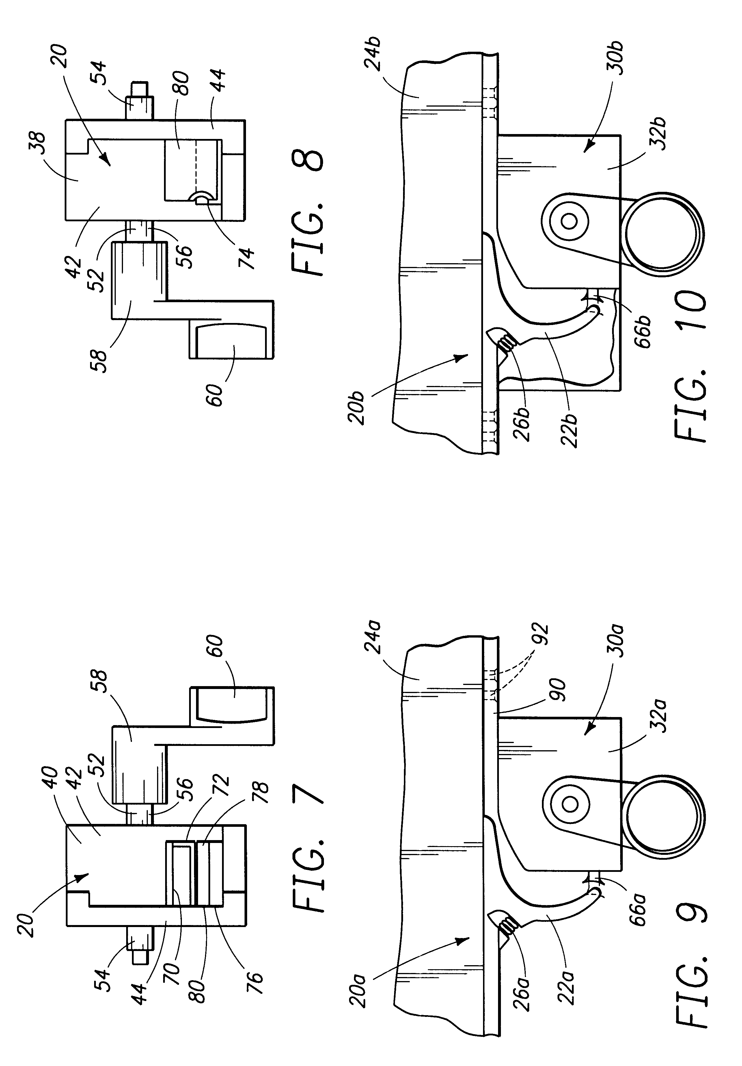
FIGS. 1-8:

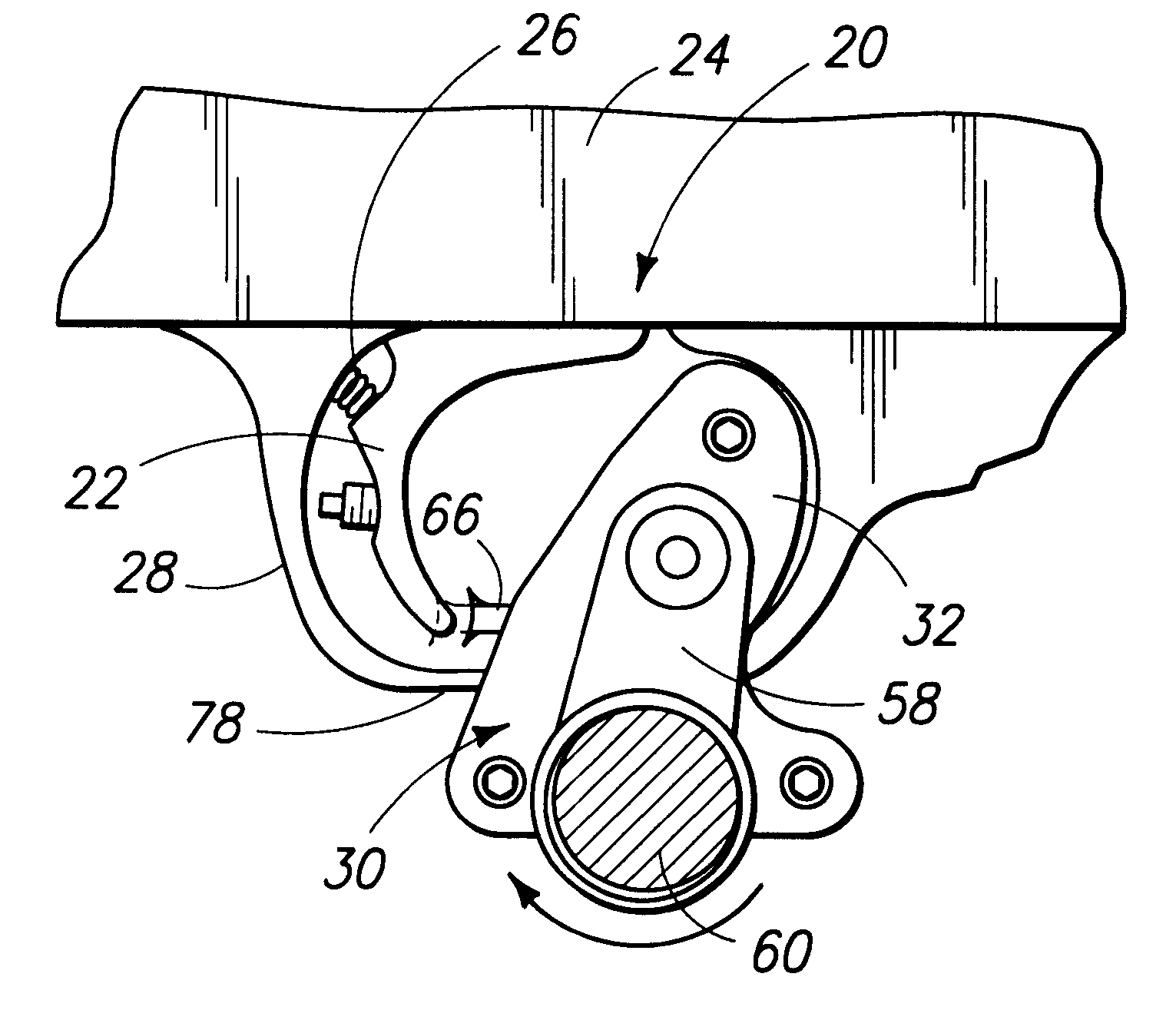
Now referring more particularly to FIGS. 1-8, inclusive, of the drawings, a first preferred embodiment of the improved gun of the present invention and the improved rapid fire trigger assembly of the present invention, shown installed thereon, is set forth, Thus, gun 20 is shown which is of conventional design and which includes a depending trigger 22 connected to the main body 24 of gun 20, with trigger 22 depending below main body 24, and with trigger 22 spring biased, as by spring 26 or the like, forwardly in the direction of the associated arrow in FIG. 1 and into the non-firing position of FIG. 1. Gun 20 also includes a generally oval trigger guard 28 connected to the bottom of main body 24 and spaced in front of, below and behind trigger 22.

Gun 20 also includes improved rapid fire trigger assembly 30 comprising housing 32 having spaced sidewalls 34 and 36 interconnected by front wall 38 and rear wall 40 to form a closed container which, however, is split into two par...


PUM


Abstract

The improved gun has a rapid fire trigger assembly. The gun has a main body and a trigger connected thereto and depending therefrom, with the lower portion of the trigger biased into a forward, non-firing position. The improved rapid fire trigger assembly includes a housing having spaced sidewalls and interconnecting front and rear sides and is adapted to be connected to the gun in front of the trigger. A generally circular elongated tube passes transversely through the housing sidewalls and into the central space in the housing. The tube is rotatable relative to the housing and has a central portion within the housing, which central portion has a number of spaced radiating spokes extending outwardly therefrom. The tube also has opposite end portions extending lateral of the housing sidewalls, one of which end portions has a crank with a trigger finger-receiving space therein. The crank is adjacent the external surface of the sidewall. A generally horizontal wall is secured in the housing central space and a slide is disposed on the top of the horizontal wall, with the front of the slide engageable with the spokes and the rear of the slide extending out a slit in the rear wall of the housing for engagement with the trigger of the gun. When the crank is rotated by a gunner's trigger finger, the central portion of the tube rotates, causing alternately rearward movement of the slide to move the trigger into a firing position, which is followed by the trigger, upon firing the gun, moving forward to the non-firing position, pushing the slide forward. Rapid sequential firing of the gun is thus effected by continuing to turn the crank. The assembly housing can be connected to the trigger guard or directly to the gun main body and can extend back around the trigger if there is not trigger guard. A wedge can be provided to wedge the housing in place against the trigger guard.

Description

1. Field of the InventionThe present invention generally relates to shooting sports equipment and more particularly to an improved gun having a novel rapid fire trigger assembly, and to the novel rapid fire trigger assembly for the gun.2. Prior ArtVarious attempts have been made to provide equipment for guns which can improve the rapidity with which the gun can be fired. Most fully automatic weapons are prohibited. Semi-automatic weapons which are not prohibited require that the gun trigger be pulled each time a shot is to be fired. When a gunner tries to pull the trigger rapidly and repeatedly, shooting accuracy decreases because of the anxiety of the gunner, because his concentration is focused on the act of repeatedly rapidly pulling the trigger instead of holding his gun aim and also because pulling or squeezing the trigger, especially when done rapidly and repeatedly, inevitably applies an angled torque to the gun through the trigger and tends to pull the gun drastically off ta...

Claims


Application Information

Patent Timeline
IPC IPC(8): F41A19/00F41A19/09
CPCF41A19/09
Inventor TRONCOSO, VINCENT
Owner TRONCOSO VINCENT
Why Eureka
Try Eureka