
Plasma display panel and method for driving the same

a plasma display panel and plasma technology, applied in the direction of gas discharge vessels/containers, instruments, electrodes, etc., can solve the problems of unstable discharge, low brightness of plasma display panels, serious drawbacks

Inactive Publication Date: 2001-05-15
SAMSUNG ELECTRONICS DEVICES CO LTD
View PDF14 Cites 18 Cited by
  • Summary
  • Abstract
  • Description
  • Claims
  • Application Information

AI Technical Summary

Benefits of technology

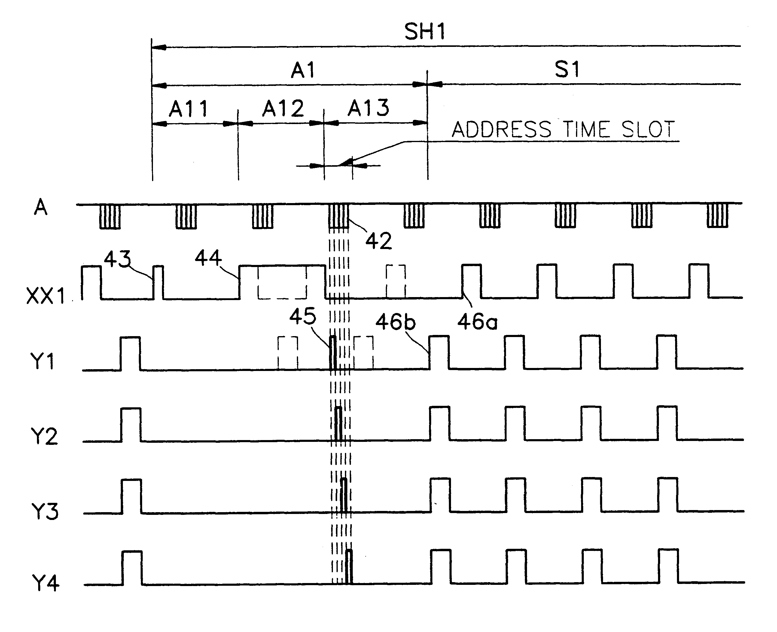
It is an object of the present invention to provide a plasma display panel in which timing of inserting an address pulse between discharge sustaining pulses is not restricted and the increase of the frequency or the voltage of discharge sustaining pulses is not required, by setting address time slot periods constructed of a plurality of data pulses between discharge sustaining pulses, dividing pairs of horizontal electrodes into a plurality of groups, each of which includes pairs of horizontal electrodes as many as the data pulses of an address time slot period and driving the pairs of horizontal electrodes, sequentially scanning the scan pulses corresponding to each data pulse during the address time slot period to each pairs of horizontal electrodes of the group, and applying to the groups a method of simultaneously addressing and sustaining discharge.

Problems solved by technology

Therefore, the brightness of the plasma display panel is very low, which is a serious drawback.
In the case of increasing the frequency of the discharge sustaining pulse, the space charge caused by the discharge generated by one pulse affects the discharge characteristic of the next discharge, since the rows of discharge sustaining pulses periodically coincide, and thus the discharge becomes unstable.
However, there are many restrictions in determining the timing for inserting the address pulses since the address pulses must be inserted between the discharge sustaining pulses.
Therefore, the number of displayable scanning lines is limited, and it is difficult to drive the addressing discharge and sustaining discharge of a high definition display.

Method used


Image

  • Plasma display panel and method for driving the same
  • Plasma display panel and method for driving the same
  • Plasma display panel and method for driving the same

Examples


Embodiment Construction

A plasma display panel according to the present invention and a method for driving the same will now be described in detail with reference to the attached drawings.

In the present invention, the electrode wiring structure and the voltage application method of a three electrode AC plasma display panel are improved so that a brightness is increased over the conventional method and the increased brightness is maintained even when the number of horizontal scanning lines increases. Namely, an address time slot constructed by a plurality of data pulses is set between discharge sustaining pulses of a three electrode AC plasma display panel. The horizontal electrodes are divided into pairs, and the pairs are arranged in groups. The number of pairs in each group is equal to the number of address time slots. One electrode of each pair of horizontal electrodes is commonly wired with the corresponding electrodes of every other group. The other electrodes are independently wired. The address time...


PUM


Abstract

An AC surface discharge plasma display panel and a method for driving the same are provided. In the method for driving the AC surface discharge plasma display panel according to the present invention, a parallel driving method is used, which is known to have better brightness characteristics than a separate driving method in which the addressing is separate from the discharge sustaining, in which the addressing and discharge sustaining are simultaneously performed. Periods between the discharge sustaining pulses applied to the scanning electrodes and the common electrodes are set as the address time slots periods, a plurality of data pulses are applied in the address time slot periods, and a number of common electrodes equal to the number of data pulses are wired as one common electrode group and are driven by the same signal, in order to solve the restrictions on the number of the horizontal scanning lines which can be scanned, which is a defect of conventional parallel drive methods.

Description

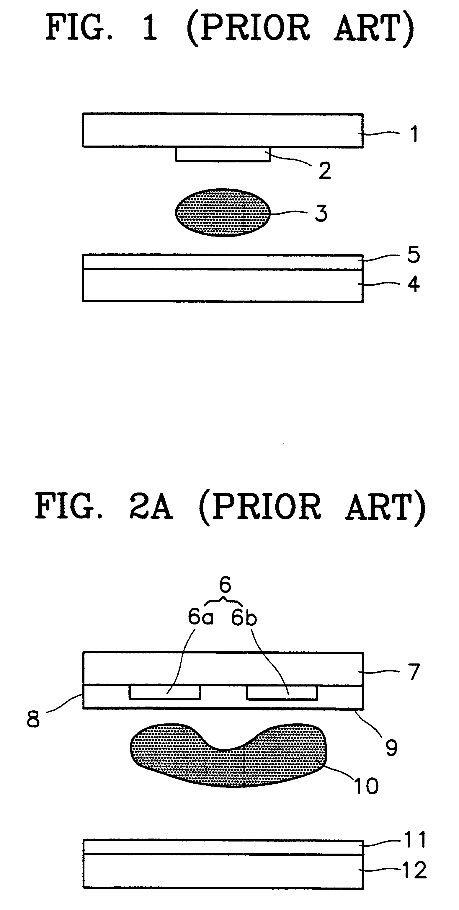
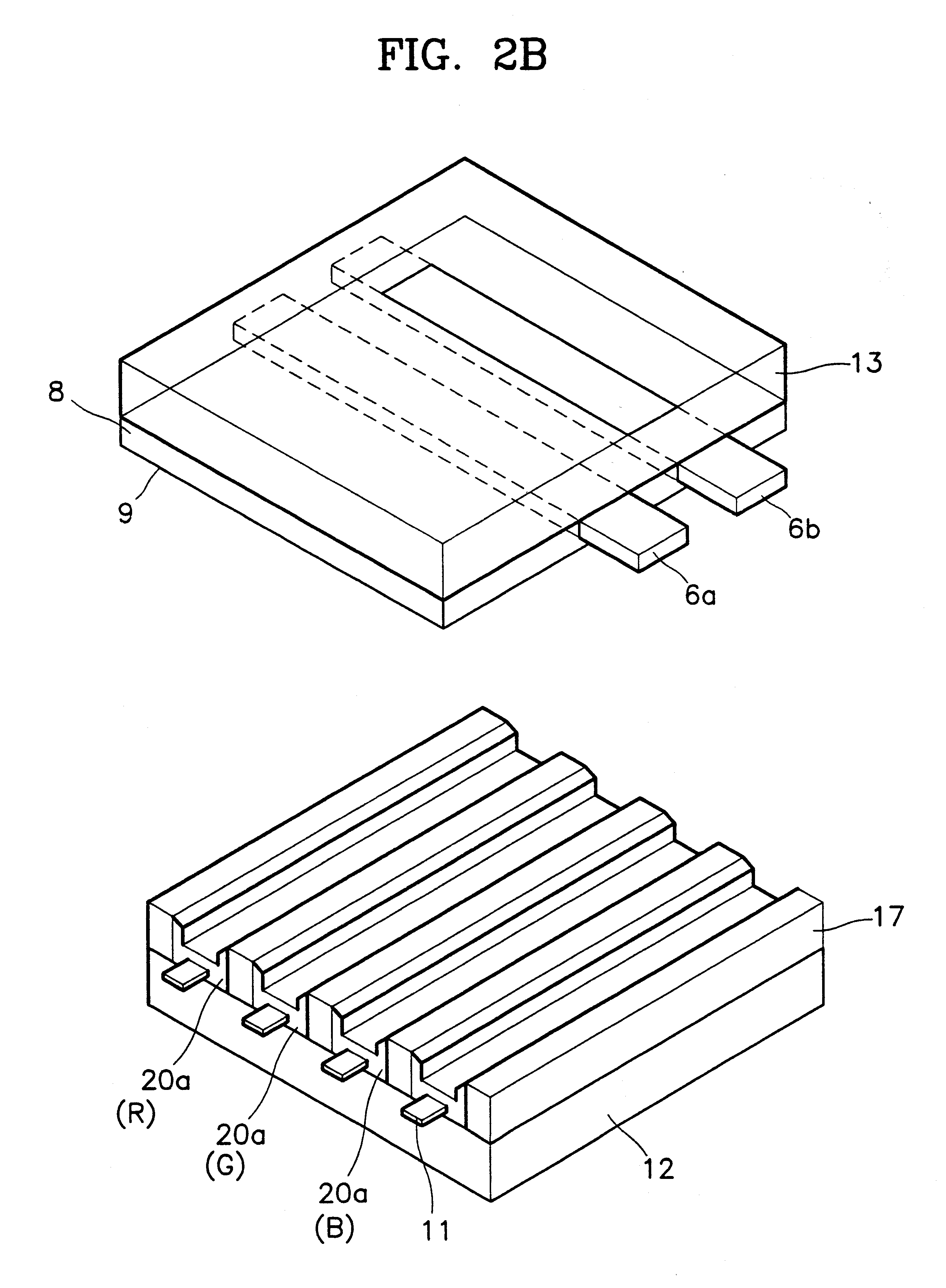
1. Field of the InventionThe present invention relates to an AC surface discharging plasma display panel, and more particularly, to a surface discharging plasma display panel according to an electrode wiring structure and a method for driving the plasma display panel for displaying gray scales.2. Description of Related ArtA plasma display panel is of a display device for displaying picture data input as an electrical signal by arranging a plurality of discharge tubes in a matrix and by selectively emitting light from them. Methods for driving the plasma display panel are divided into DC driving methods and AC driving methods according to whether the polarity of a pulse voltage applied in order to sustain the discharge changes over time.FIG. 1A is a sectional view of a DC opposite surface discharge plasma display panel. FIGS. 2A and 2B are respectively a sectional view and perspective view of an AC surface discharge plasma display panel. As shown in the drawings, in both DC and AC ty...

Claims


Application Information

Patent Timeline
IPC IPC(8): G09G3/28G09G3/20G09G3/288G09G3/291G09G3/293G09G3/294G09G3/296G09G3/298H01J11/12H01J11/14H01J11/22H01J11/24H01J11/26H01J11/34
CPCG09G3/293G09G3/298G09G3/291G09G2310/0216G09G2310/0218
Inventor FUKUSHIMA, MASAKAZURYEOM, JEONG-DUK
Owner SAMSUNG ELECTRONICS DEVICES CO LTD
Learn More