
Method and apparatus for tracking position of a ball in real time

Inactive Publication Date: 2001-05-15
ALCATEL-LUCENT USA INC +1
View PDF7 Cites 127 Cited by
  • Summary
  • Abstract
  • Description
  • Claims
  • Application Information

AI Technical Summary

Problems solved by technology

However, the only conventional form of tennis ball tracking currently available is a radar gun used to measure speed of service.
In addition, real time tracking of objects such as athletes or balls in a sporting event is challenging, especially because it is difficult to obtain a clean segmentation of the ball from the background in view of changing lighting conditions, variations in clothing worn by athletes (especially with regard to color), differences in the characteristics (for example, reflectivity) of playing surfaces (grass, clay, hardwood, ice, etc.), and the fast and dynamic movement of athletes.
However, these conventional systems do not yield a single motion region or even a consistent set of motion regions, which deficiencies are exacerbated when tracking athletes, balls, pucks, and like in the midst of highly dynamic movement.
Specifically, the MLD system requires several frames before a good object separation is obtained, and no criteria is provided for determining when satisfactory object separation has occurred.
In addition, no mechanism is provided for propagating the generated clusters to prior and subsequent frames for continuity in the motion representation.
This undermines real time operation.

Method used


Image

  • Method and apparatus for tracking position of a ball in real time
  • Method and apparatus for tracking position of a ball in real time
  • Method and apparatus for tracking position of a ball in real time

Examples


Embodiment Construction

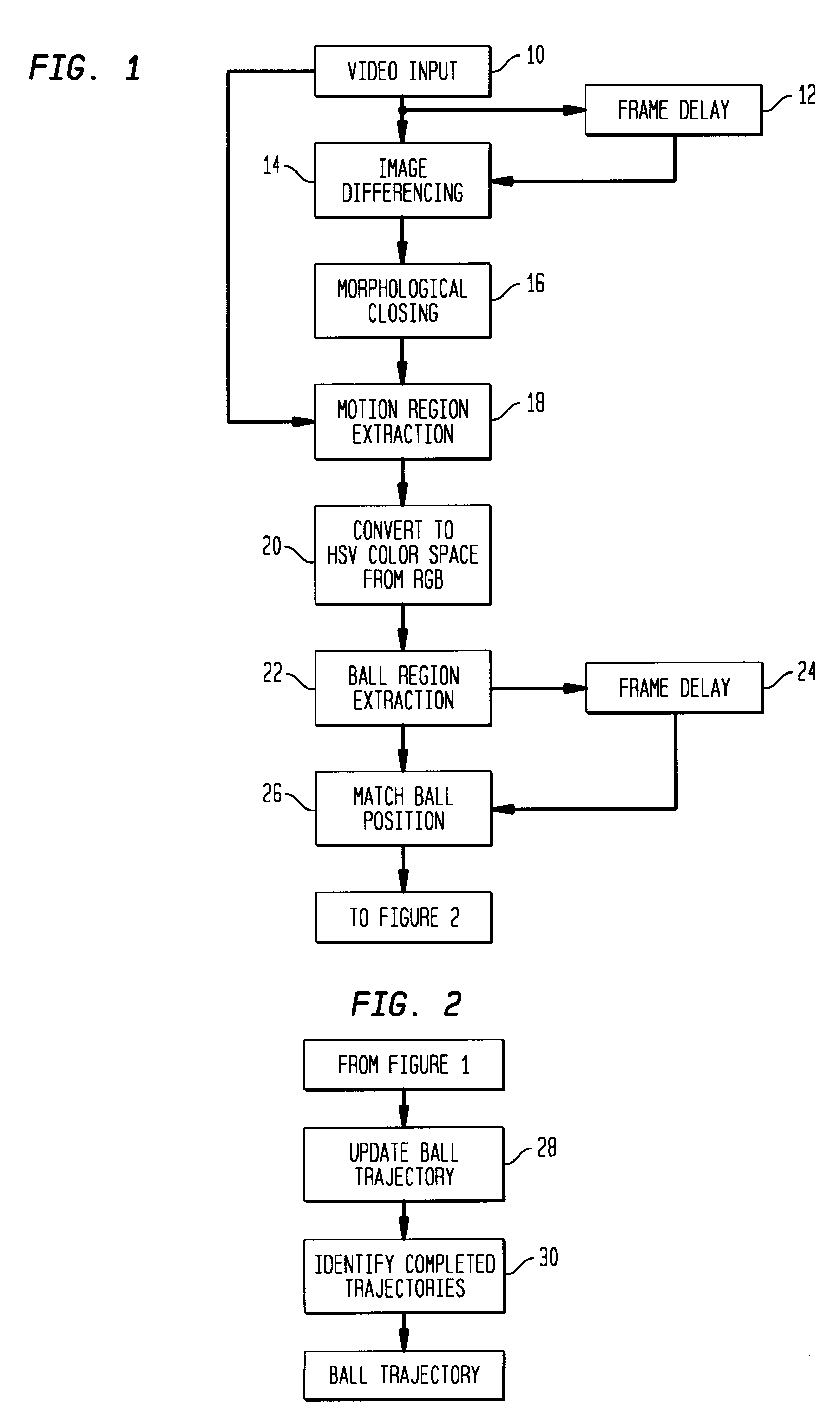
The present invention will now be described in detail with reference to FIGS. 1 and 2, which collectively illustrate a basic method for tracking, by way of example, a tennis ball according to the present invention.

As seen in FIGS. 1 and 2, a video input is passed through a frame delay 12 in order to provide a current and previous frame, which are differenced (and preferably also thresholded) in step 14. Differencing and thresholding in this manner is particularly desirable as it is a fast operation which works across a variety of lighting conditions.

The video input 10 is either already in digital form using a digital video camera, or is an analog input passed through a conventional digitizer (not shown).

The result of the image differencing step 14 is a binary image. Small gaps or other discontinuities in the binary image may be closed using a conventional morphological closing operation, comprising dilation and erosion steps, as is conventional (see, for example, Giardina et al., "M...


PUM


Abstract

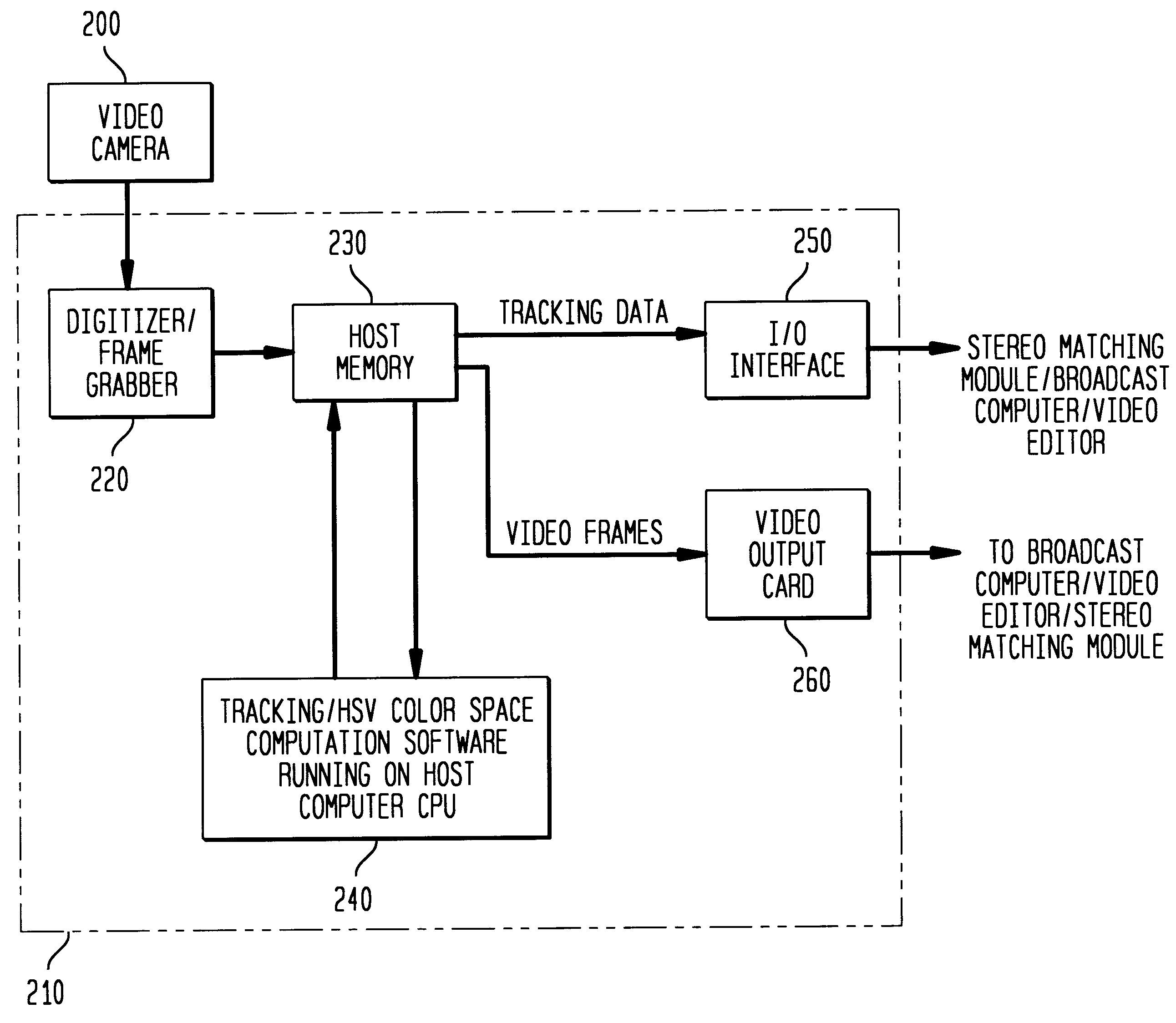
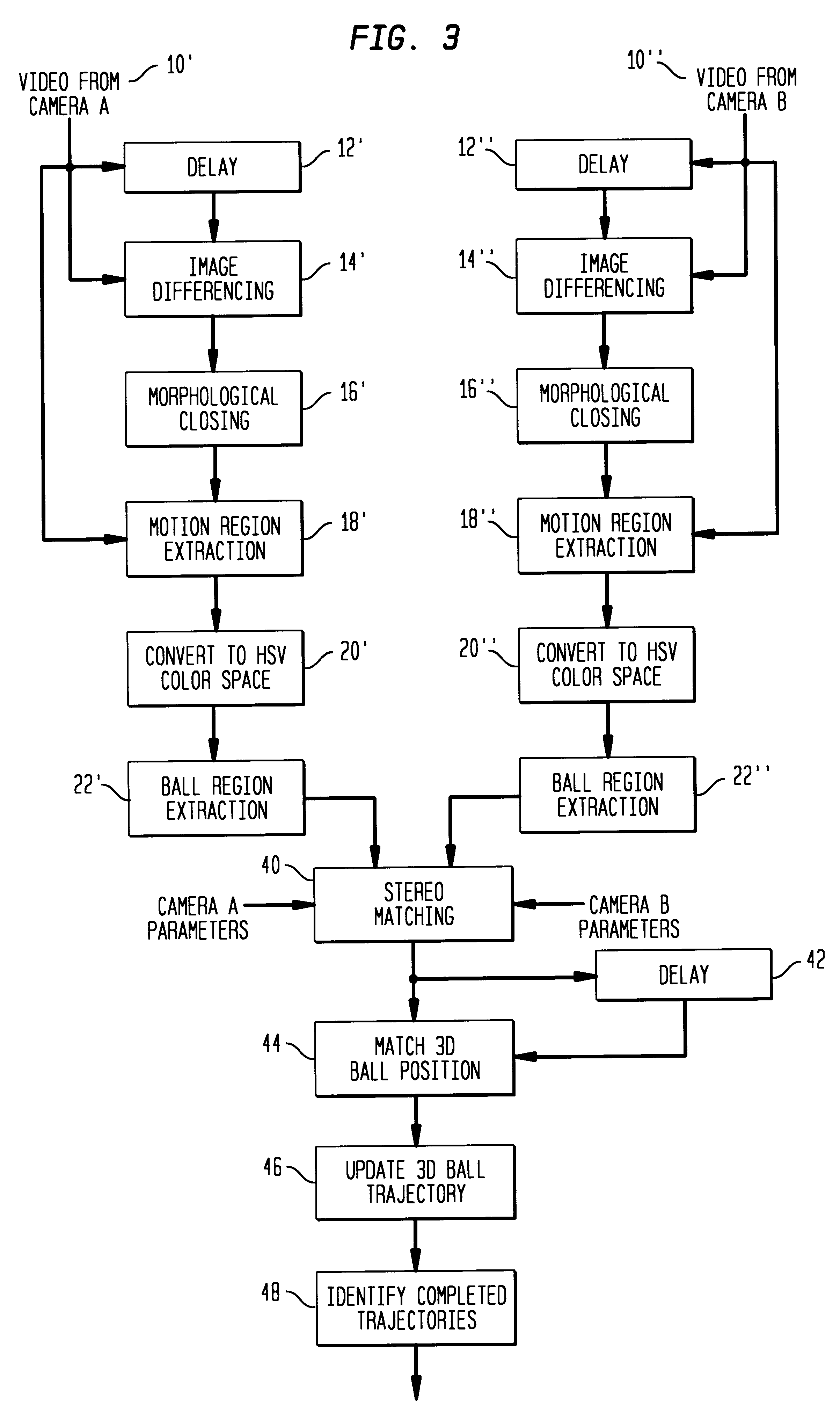
A method and apparatus for tracking objects used in connection with athletic activities or sporting events, especially, balls, pucks, and the like. The method includes the steps of differencing present and previous frames of a video image including the, for example, ball to obtain motion regions, converting the motion regions to HSV color space, extracting the region corresponding to the ball based on empirical color data about the ball, obtaining a motion vector based on the motion of the ball region from a previous frame to the current frame, and updating the ball trajectory based on the newest motion vector obtained. The method also preferably includes a step of identifying completed trajectories based on preset constraints. The method is preferably expanded on by using at least one pair of cameras to provide a three-dimensional trajectory, and sometimes preferable expanded on by using a plurality of cameras, especially a plurality of pairs of cameras. An apparatus according to the present invention includes at least one camera connected to a computer which operates to difference previous and current frames, compute the ball track, convert ball regions to HSV color space and output the tracking and video information. In a case where one or more pairs of cameras are used, the computer is preferably also provided with a stereo matching device or module for matching the tracking results from respective cameras and / or respective pairs of cameras.

Description

1. Field of the InventionThe present invention relates to a method and apparatus for tracking moving objects in real time whereby trajectories corresponding to the movement of the objects are determined. More particularly, the present invention relates to a method and apparatus for tracking moving objects, such as balls, pucks, and the like, in connection with sporting events and exploiting such tracking to derive information corresponding to the movement of the objects being tracked. The present invention particularly relates to a method and apparatus for tracking an object such as a tennis ball.2. Description of Related ArtOne field in which real time tracking would be particularly desirable, but is not currently greatly utilized, is in the field of sports. For example, continuous tracking of a tennis ball during a tennis match provides valuable information about the skill and strategy of a player because information such as ball speed and ball placement would be readily obtainabl...

Claims


Application Information

Patent Timeline
IPC IPC(8): G01S3/786G01S3/78H04N7/18H04N13/00G06V10/24
CPCG01S3/7865G06K9/32H04N7/18G06T7/204G06T7/2053H04N13/0003H04N13/0221H04N13/0239H04N13/0242H04N2013/0081H04N2013/0085H04N2013/0092G06T2207/10021G06T2207/10024G06T2207/20036G06T2207/30224G06T2207/30241G06T7/248G06T7/254H04N13/243H04N13/221H04N13/10H04N13/239G06V10/24
Inventor CARLBOM, INGRID B.JEAN, YVES D.PINGALI, SARMA VGK
Owner ALCATEL-LUCENT USA INC
Learn More