Wheel balance weight

a technology of wheel balance and weight, which is applied in the direction of rotating body balancing, mechanical equipment, transportation and packaging, etc., can solve the problems of increasing the number of parts, vibration and noise, and increasing the manufacturing cost of wheel balance weight,

Inactive Publication Date: 2001-05-29
TAIHO INDUSTRIES CO LTD +1
View PDF16 Cites 59 Cited by
  • Summary
  • Abstract
  • Description
  • Claims
  • Application Information

AI Technical Summary

Problems solved by technology

In a wheel assembly in which a tire of an automobile and the like is assembled into a rim of a wheel, if an unbalance of the wheel assembly in a circumferential direction around a rotating shaft or in an axial direction becomes larger, various defects such as a vibration or a noise will be generated in running of the automobile.
These vibration and noise are resulted from the unbalance of the wheel, and a wheel balance weight is attached to the wheel to remove the unbalance.
However, since the material containing the lead has a problem in an influence to a natural environment, the wheel balance weight which has the weight body made of an iron or an alloy of iron has been developed.
However, the wheel balance weight disclosed in Japanese U.M. No.3046046 has an disadvantage that the numbers of parts and a manufacturing cost of the wheel balance weight increase, since the engaging member is fixed to the weight body by riveting.
On the other hand, the wheel balance weight disclosed in Japanese U.M. Laid-open No.62-70001 has an disadvantage that the fixing of the engaging member to the weight body is not sufficient, since only a top of the protruded portion is engaged with a periphery of the through-hole.
Also, the manufacturing cost of the weight body increases due to of the protruded portion formed within the recessed groove.

Method used


Image

  • Wheel balance weight
  • Wheel balance weight
  • Wheel balance weight

Examples


first embodiment

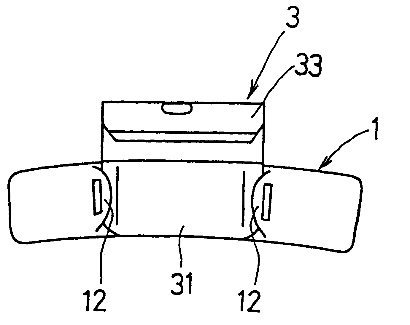
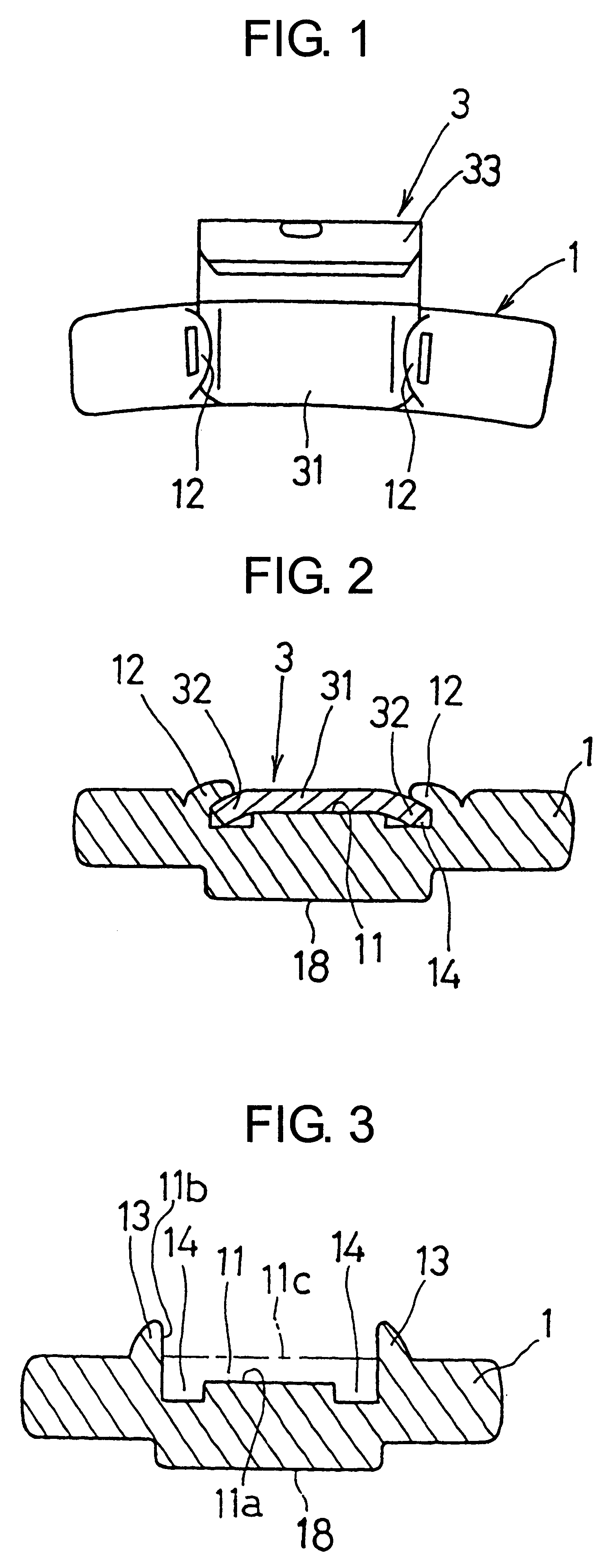
the wheel balance weight is shown in FIGS. 1 and 2, in which FIG. 1 is a plan view of the wheel balance weightand FIG. 2 is a cross-section of the same.

This wheel balance weight is comprised of a weight body 1 and an engaging member 3. The weight body 1 is manufactured by cold-forging the rod steel cutted by a predetermined length, and has an opened engaging groove 11 at an upper surface thereof. The engaging groove 11 has a predetermined width (up / down direction in FIGS. 1 and 2) in a longitudinal direction (right / left direction in FIGS. 1 and 2) of the weight body 1 and depth (up / down direction in FIG. 2), and extend in full width (up / down direction in FIG. 1) of the weight body 1. The engaging groove 11 is defined by a bottom wall surface 11a, a pair of side wall surfaces 11b, and an opened surface 11c. The weight body 1 also has a low protruded bead 18 at a lower surface thereof. The engaging groove 11 has, at both ends or sides thereof, a pair of deep grooves 14 deeper than the...

second embodiment

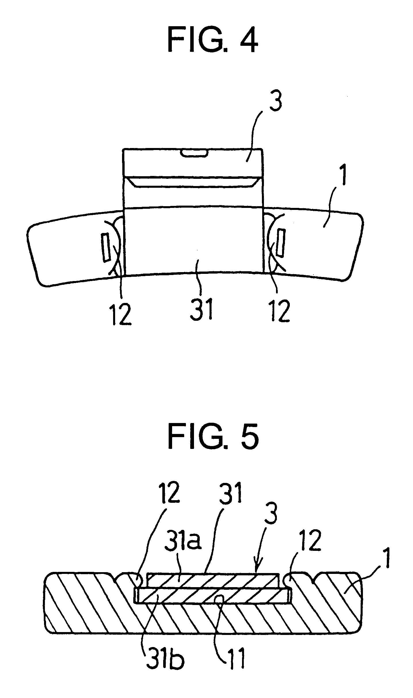
the balance weight is shown in FIG. 4 and FIG. 5. This wheel balance weight is comprised of a weight 1 and an engaging member 3. The weight body 1 has a recessed or concave engaging groove 11 at a central portion thereof on a surface opposing to the wheel and a pair of protruded portions 13 protruded toward the engaging groove 11 from the both side portions thereof. The engaging member 3 has one end portion 31 of a double construction formed by folding back an end of the metallic plate to have a opened side portion 31a and a bottom surface side portion 31b, and both side edge portions of the opened side portion 31a is removed to reduce the width.

The pawl portion 12 is formed, in the state where the one portion 31 of the engaging member 3 is fitted into the engaging groove 11 of the weight body 1, by caulking the both side portions defining the engaging groove 11 toward or over the one end portion 31 to form the pawl portions 12. Thus, the pawl portions 12 press the wide area of the ...

third embodiment

the wheel balance weight is shown in FIG. 5 and FIG. 6. This wheel balance weight is an improvement of the wheel balance weight of the second embodiment, and is comprised of a weight body 1 and an engaging member 3. The weight body 1 is provided with a first guiding portion 15 (a protrusion) protruded from a central portion of a bottom surface of an engaging groove 11, while the engaging member 3 is provided with a second guiding portion 35 (a through-hole) formed at a central portion of the one end portion 31 of double construction.

When the engaging member 3 is fixed to the weight body 1, the first guiding portion 15 is fitted into the second guiding portion 35 to position the one end portion 31 of the engaging member 3 within the engaging groove 11 of the weight body 1. Then, a head portion of the first guiding portion 15 is caulked over a periphery of the second guiding portion 35. Then, the protruded portion 13 is caulked over the side edge portion of the one end portion 31 to f...


PUM


Abstract

A wheel balance weight attached to a wheel of an automobile. The weight body has an engaging groove with which one end portion of the engaging member engages. Opened end portions of the weight body defining the engaging groove are caulked over the one end portion to form pawl portions. Thus, the one end of the engaging member is fixed to the engaging groove of the weight body.

Description

1. Field of the InventionThis invention relates to a wheel balance weight attached to a wheel of an automobile.2. Related ArtIn a wheel assembly in which a tire of an automobile and the like is assembled into a rim of a wheel, if an unbalance of the wheel assembly in a circumferential direction around a rotating shaft or in an axial direction becomes larger, various defects such as a vibration or a noise will be generated in running of the automobile. These vibration and noise are resulted from the unbalance of the wheel, and a wheel balance weight is attached to the wheel to remove the unbalance.A conventional wheel balance weight is comprised of a weight body made of a lead or a lead alloy and has a predetermined weight, and a clip for fixing the weight body to the wheel. The weight body and the clip are integrally formed by a casting. The lead or lead alloy constituting the weight body is selected due to a large specific gravity thereof and a soft, adaptable character thereof to ...

Claims


Application Information

Patent Timeline
Patent Type & Authority Patents(United States)
IPC IPC(8): F16F15/00F16F15/32
CPCF16F15/324
Inventor SUGAYAUCHI, TATSUHIKOYAMAGUCHI, OSAMU
Owner TAIHO INDUSTRIES CO LTD
Why Eureka
Try Eureka