Magnetic switch

a technology of magnetic switch and switch body, applied in the field of magnetic switch, can solve the problems of irratic operation and malfunction, no easy way to tell if the membrane has been compromised, and no established basis

Inactive Publication Date: 2001-06-12
UNITED STATES OF AMERICA THE AS REPRESENTED BY THE SEC OF THE ARMY
View PDF3 Cites 36 Cited by
  • Summary
  • Abstract
  • Description
  • Claims
  • Application Information

AI Technical Summary

Problems solved by technology

In the event of use in an unclean environment, such as an explosive atmosphere, the common type switch will be exposed to pollutants, causing irratic operation and malfunctions.
Push button, toggle and microswitches, which are used in an unclean atmosphere having a flexible membrane around them, deteriorate after repeated making them unsafe.
There is no easy way to tell if the membrane has been compromised.
While the prior art has reported using switches none have established a basis for a specific magnetic switch that is dedicated to the task of resolving the particular problem at hand.

Method used


Image

  • Magnetic switch
  • Magnetic switch

Examples


Embodiment Construction

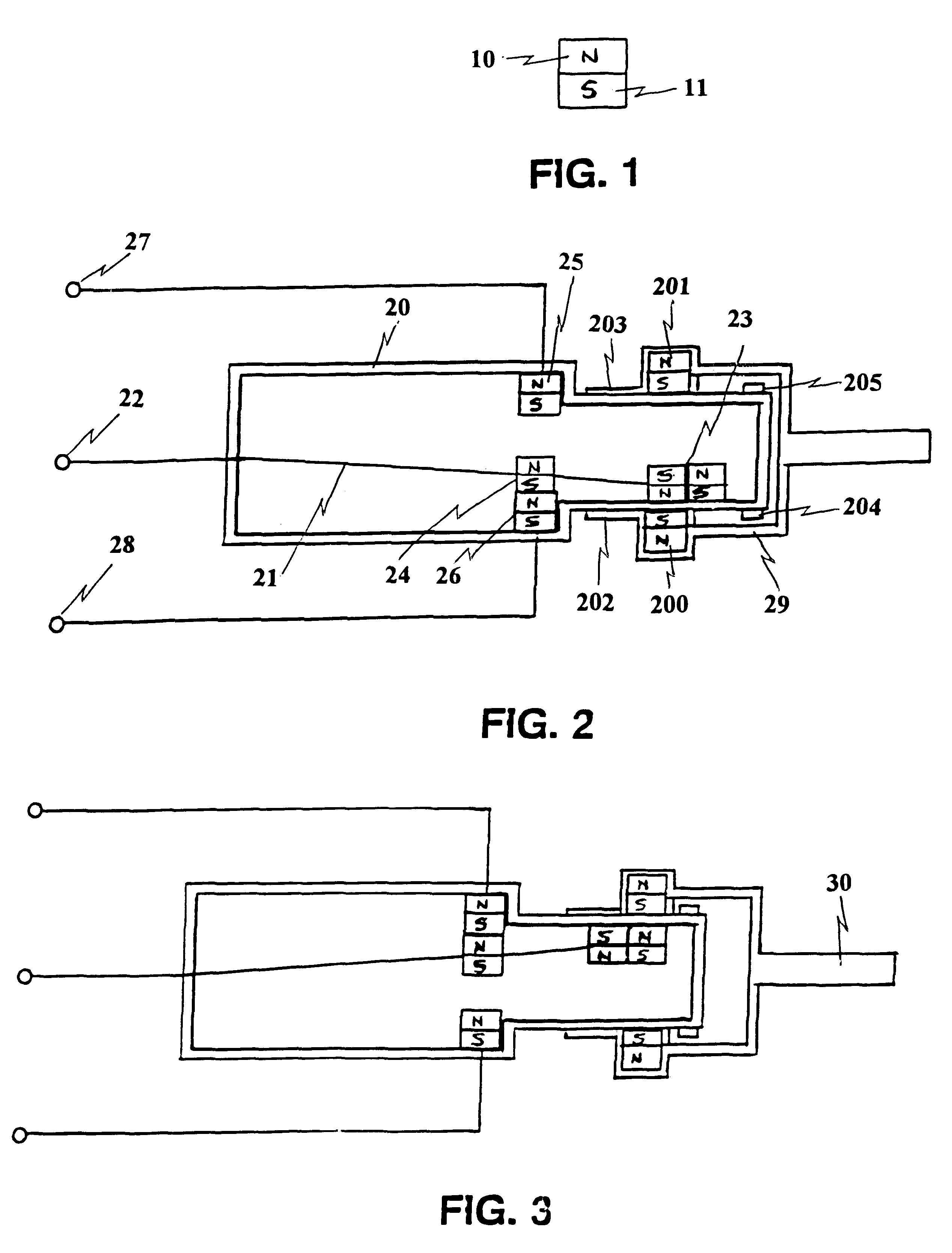
Referring now to the drawings, and more particularly to FIG. 1, there is shown a side view of a magnet utilized as contact magnets and source magnets for the magnetic switch of the present invention. Portion 10 is the north pole and portion 11 is the south pole for the permanent magnet shown in FIG. 1. In an alternative embodiment, contact surfaces that provide electrical contact are treated with a coated surface such that high voltage may be utilized in the invention thus preventing arcing.

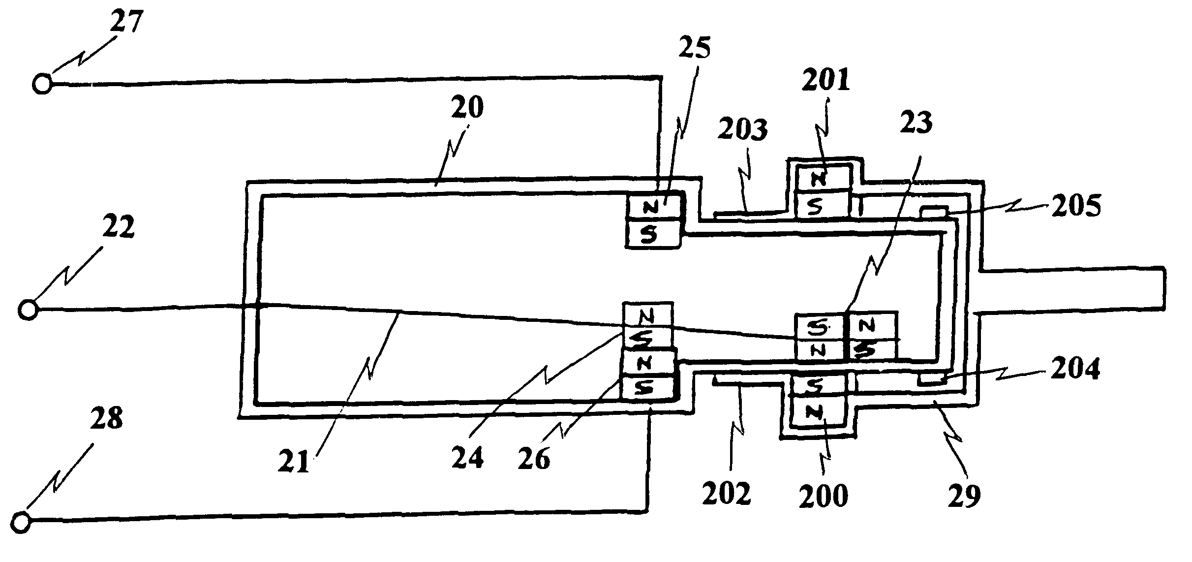
FIG. 2 is a side view of the magnetic switch with magnetic activation means pushed in. Sealed encasement 20 is shown with an inside and outside surface. Flexible metallic strip 21 has two ends as shown in FIG. 2. End 22 provides an electrical terminal to effect electrical contact outside of sealed encasement 20. Magnetic responsive means 23 is integrated to the other end of flexible metallic strip 21 within sealed encasement 20. In the preferred embodiment, magnetic responsive means 23 is a perma...


PUM


Abstract

A magnetically activated switch includes a flexible metallic strip on the inside of a sealed encasement, having first and second ends. The first end provides for an electrical contact and extends through the wall of the sealed encasement, with the strip being firmly secured by the wall of the encasement at the exit point, leaving the second end unsupported and having a magnetic responsive element attached. A first dipole magnet is coupled to the flexible metallic strip and located within the sealed encasement, intermediate the first and second ends. Second and third dipole magnets are diametrically opposed and separate to each other where each of the second and third dipole magnets are fixedly coupled to the inside surface of the sealed encasement. Two electrical terminals coupled respectively to the second and third dipole magnets extending through the sealed encasement. A magnetic activation device in sliding engagement with the outside surface of the sealed encasement effects the movement of the magnetic contact by sliding to first and second positions corresponding to alignment of the second and third dipole magnets creating an electrical circuit flowing from the flexible metallic strip to one of said two electrical terminals.

Description

1. Field of the InventionThe present invention generally relates to magnetic switches, and more specifically, to a switch that can be activated solely by the selective movement of external magnets in close proximity to internally encapsulated magnets.2. Description of Prior ArtSwitching mechanisms are utilized to make, break, or change the current flow of an electrical circuit. Most switches consist of at least two or more contacts mounted on a structure and arranged so that the contacts can be moved into and out of physical contact with each other by a suitable operating mechanism. The common switch utilizes electrical power in the operating mechanism, whereas a common desired effect is a fast snap switching action between contact to reduce arcing. In the event of use in an unclean environment, such as an explosive atmosphere, the common type switch will be exposed to pollutants, causing irratic operation and malfunctions.Push button, toggle and microswitches, which are used in an ...

Claims


Application Information

Patent Timeline
Patent Type & Authority Patents(United States)
IPC IPC(8): H01H36/00
CPCH01H36/0073
Inventor FRIEDMAN, MELVIN H.
Owner UNITED STATES OF AMERICA THE AS REPRESENTED BY THE SEC OF THE ARMY
Why Eureka
Try Eureka