
Seatback for automobile

a seatback and automobile technology, applied in the direction of vehicle components, pedestrian/occupant safety arrangements, vehicle arrangements, etc., can solve the problems of horizontal portion affecting the shoulder of the occupant delay of movement and reduction of an operation amount of the headres

Inactive Publication Date: 2001-06-26
IKEDA BUSSAN CO
View PDF10 Cites 123 Cited by
  • Summary
  • Abstract
  • Description
  • Claims
  • Application Information

AI Technical Summary

Benefits of technology

The present invention is to provide a seatback for an automobile where rubbing noises do not occur between the pressure receiving member and the pad, even when a rearward load from an occupant acts on the pressure receiving member, so that an operation amount of the headrest can securely be secured.

Problems solved by technology

In such a technique, however, there is a drawback that, when a horizontal portion of the supporting means positioned on the pressure receiving member is pivoted about a upper frame portion of the seatback frame as a pivoting fulcrum, the horizontal portion may interfere with a shoulder of the occupant.
That is, as described above, there is a drawback that the supporting means is not rotated so that the headrest may be prevented from approaching to the head of the occupant.
Also, there is a drawback that since the pressure receiving member is made of cloth, it is flexed, so that a rearward load of the occupant may not be transmitted securely to the pressure receiving member, which results in delay of movement and reduction of an operation amount of the headrest.
Furthermore, in these conventional arts, there is a drawback that, since the pressure receiving member is made of cloth, rubbing noises may occur between the cloth and the pad, which is required to be improved for comfortability in the vehicle.
Also, there is a drawback that, as the pressure receiving member is made of cloth, a flexing amount thereof is increased so that rearward load of the occupant may not be securely transmitted to the pressure receiving member, which results in delay of movement and reduction of an operation amount of the headrest.

Method used


Image

  • Seatback for automobile
  • Seatback for automobile
  • Seatback for automobile

Examples


first embodiment

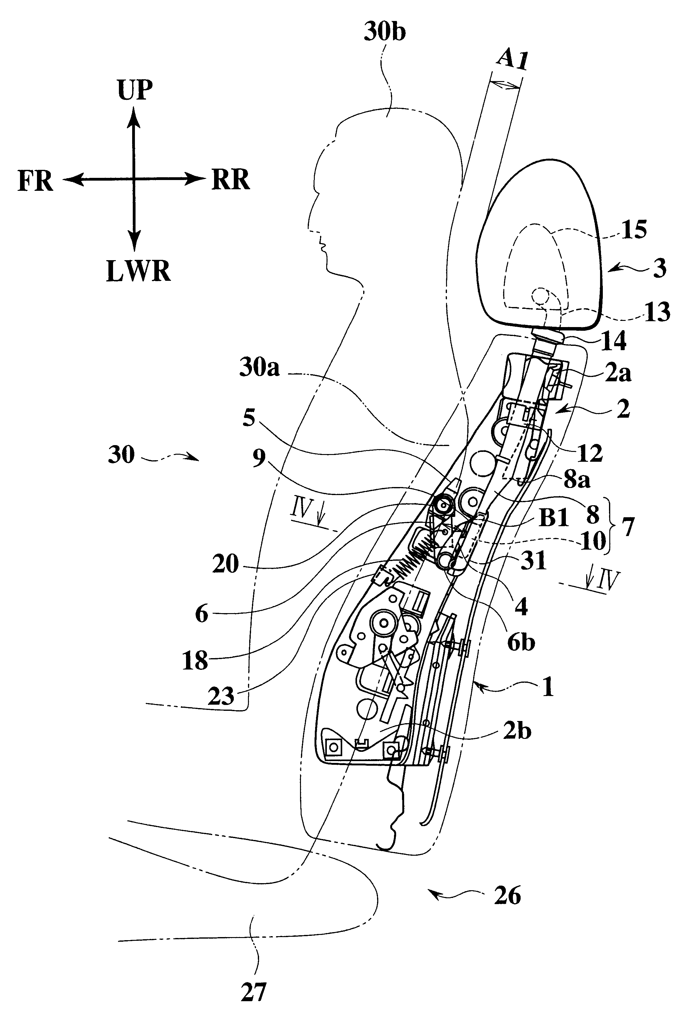
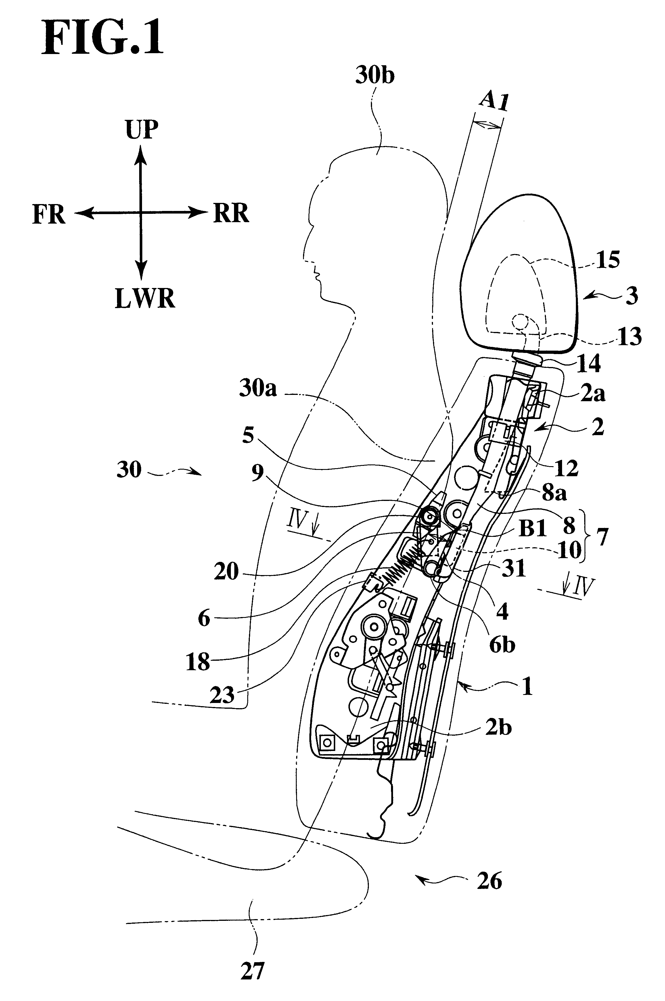
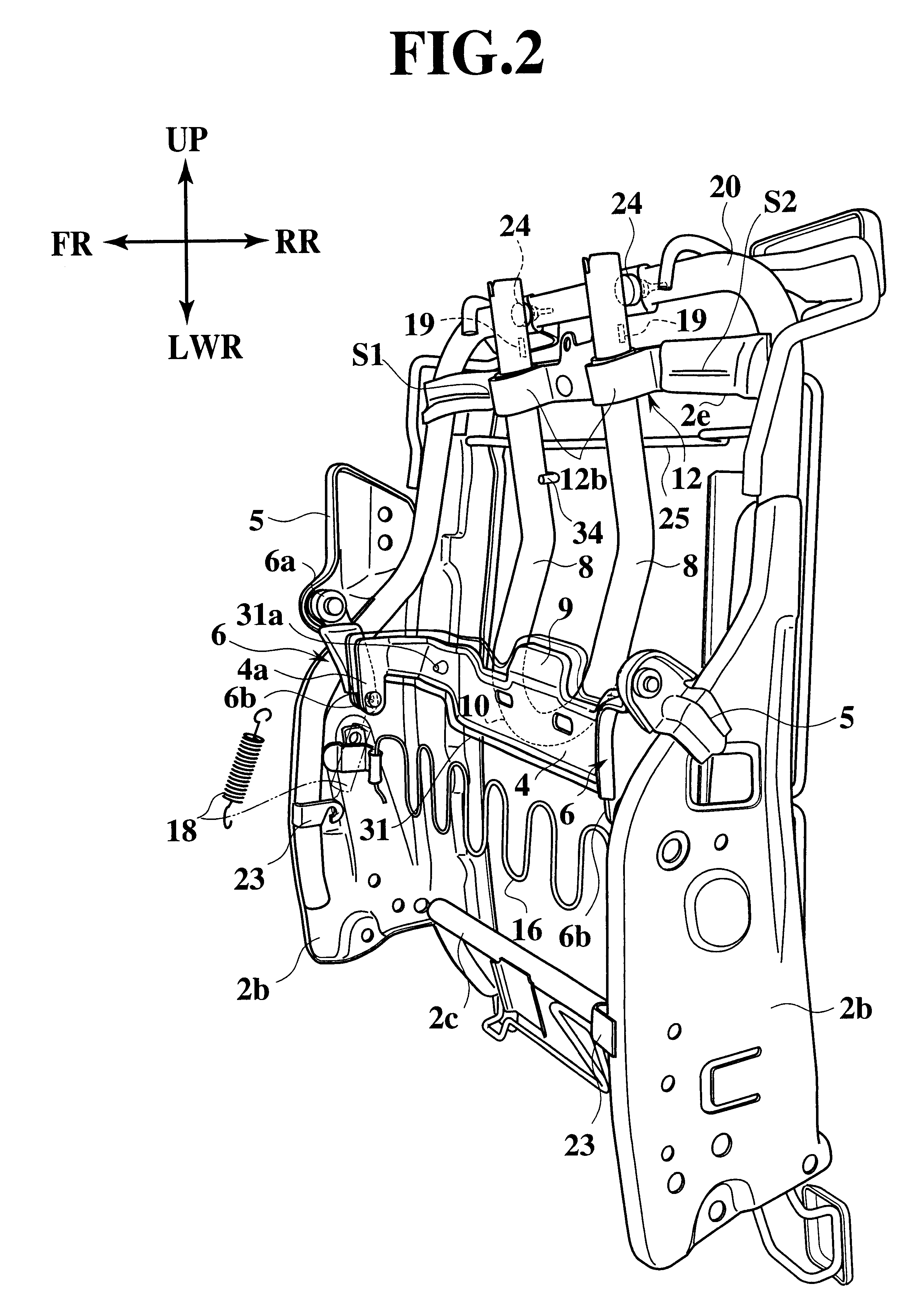
FIGS. 1 to 5 show an embodiment of the present invention, where reference numeral 1 denotes a seatback for an automobile and 3 denotes a headrest.

The seatback 1 is composed of at least a seatback frame 2, pads (not shown) formed of polyurethane foam and disposed at a front side and a rear side of the seatback frame 2, and an outer skin made of cloth for covering the pads or the like.

The seatback frame 2 comprises an upper frame 2a formed in an inverse U-shaped configuration where its one leg portion is long and the other leg portion is short (for securing a space for attaching an airbag apparatus (not shown)), left and side symmetrical side frames 2b disposed at positions suspended from left and right end portions of the upper frame 2a and an under frame 2c bridged between lower end potions of the side frames 2b.

Brackets 5, each being formed of a steel plate in a plate shape, are respectively on the side frames 2b. One end portions 6a of operation links 6 are respectively supported ...

second embodiment

A second embodiment shown in FIGS. 6 to 8 has the almost same structure as the first embodiment. Same element are given same reference characters, and detail explanation to them is omitted.

Also, in FIG. 8, there is the headrest shown with a double dotted line and indicated by reference numeral 3, and the headrest 3 shown with the double dotted line shows a position of the headrest 3 in a case where it is not moved. In such a case, the head 30b of the occupant 30 is moved as shown with a fine double dotted line.


PUM


Abstract

There are provided a headrest; a seatback frame; a supporting member which was kept by the seatback frame, supports the headrest to be swung, and is arranged at least inside a shoulder point of AFO 5% tile mannequin from a front view thereof; and a pressure receiving member which is formed of a rigid body, is supported by the supporting member, and is to receive a predetermined pressure to swing the supporting member. Preferably, the pressure receiving member has a cross-sectional configuration formed in an almost U-shape, and is spaced from a back face of a pad arranged in front of the pressure receiving member.

Description

1. Field of the InventionThe present invention relates to a seatback for an automobile, and particularly to a seatback structure for an automobile protecting the cervical vertebrae of a vehicle occupant when his / her own automobile is collided with another vehicle.2. Description of the Relevant ArtAs disclosed in International Patent 98 / 09838 Official Gazette, a conventional seatback for an automobile comprises at least a seatback frame, supporting means supported rotatably in forward and rearward direction at an upper end portion of the seatback frame, a headrest supported movably in a vertical direction at an upper end portion of the supporting means via a stay, a pressure receiving member supported at a lower end portion of the supporting means and receiving pressure from the back of a vehicle occupant, operating link rotatably pivoted to the seatback frame and the pressure receiving member, and a pad disposed ahead of the pressure receiving member.Then, since the headrest instant...

Claims


Application Information

Patent Timeline
Patent Type & Authority Patents(United States)
IPC IPC(8): B60N2/48
CPCB60N2/4838B60N2/4885B60N2002/4897B60N2/838B60N2/888B60N2/897
Inventor NAKANO, NOBUYUKIHIRABAYASHI, SHIGEKI
Owner IKEDA BUSSAN CO
Learn More