Interventional MR surgical table

Inactive Publication Date: 2005-09-20
RGT UNIV OF MINNESOTA
View PDF12 Cites 34 Cited by
  • Summary
  • Abstract
  • Description
  • Claims
  • Application Information

AI Technical Summary

Benefits of technology

[0006]The invention further provides method and apparatus for supporting a patient's body on an elongate member with a substantially planar surface, the elongate member having a longitudinal axis, positioning the member inside a bore of a MR scanner so that at least a porti

Problems solved by technology

However, these designs have been first efforts and have not bee

Method used


Image

  • Interventional MR surgical table
  • Interventional MR surgical table
  • Interventional MR surgical table

Examples


first embodiment

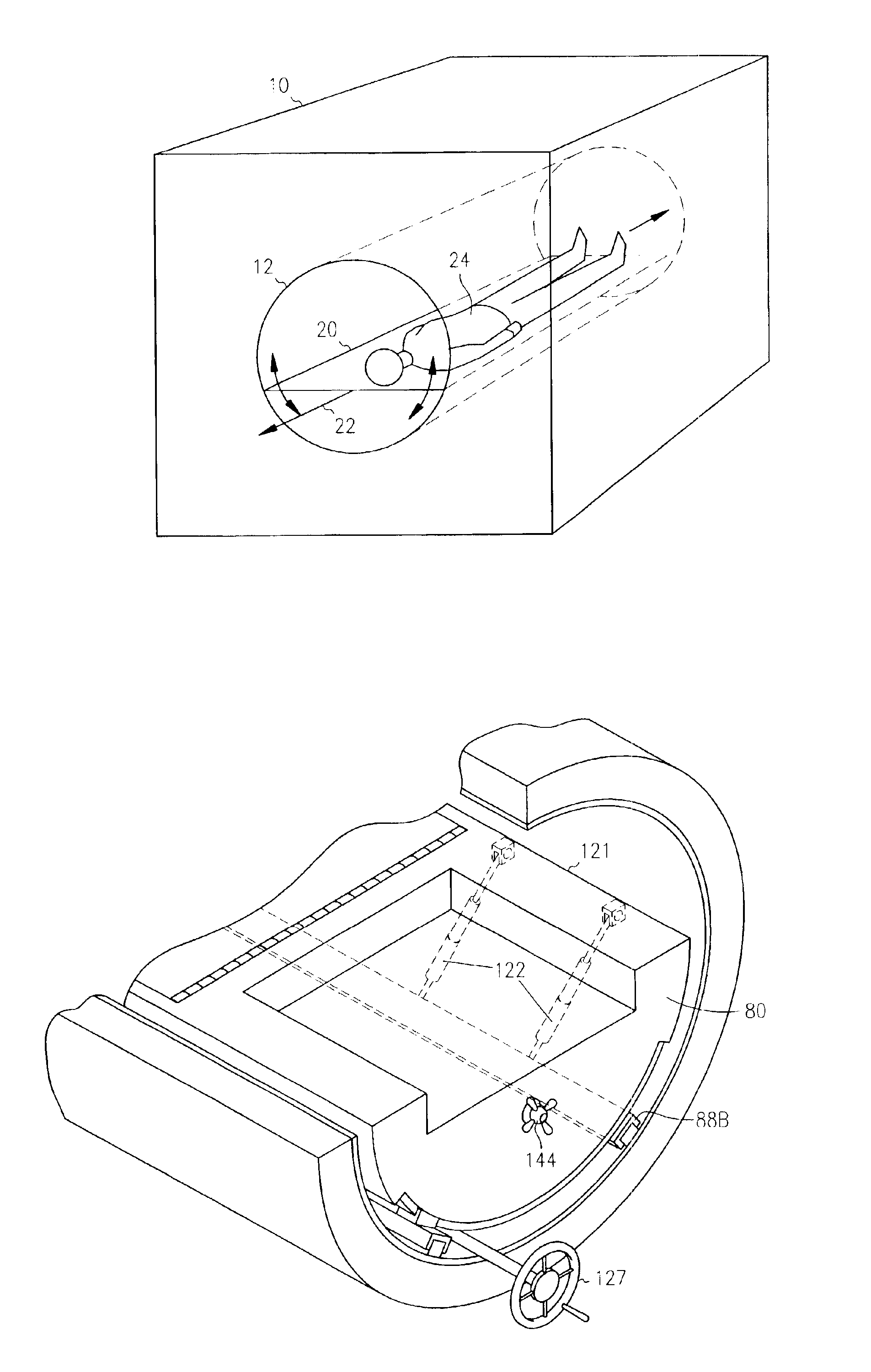
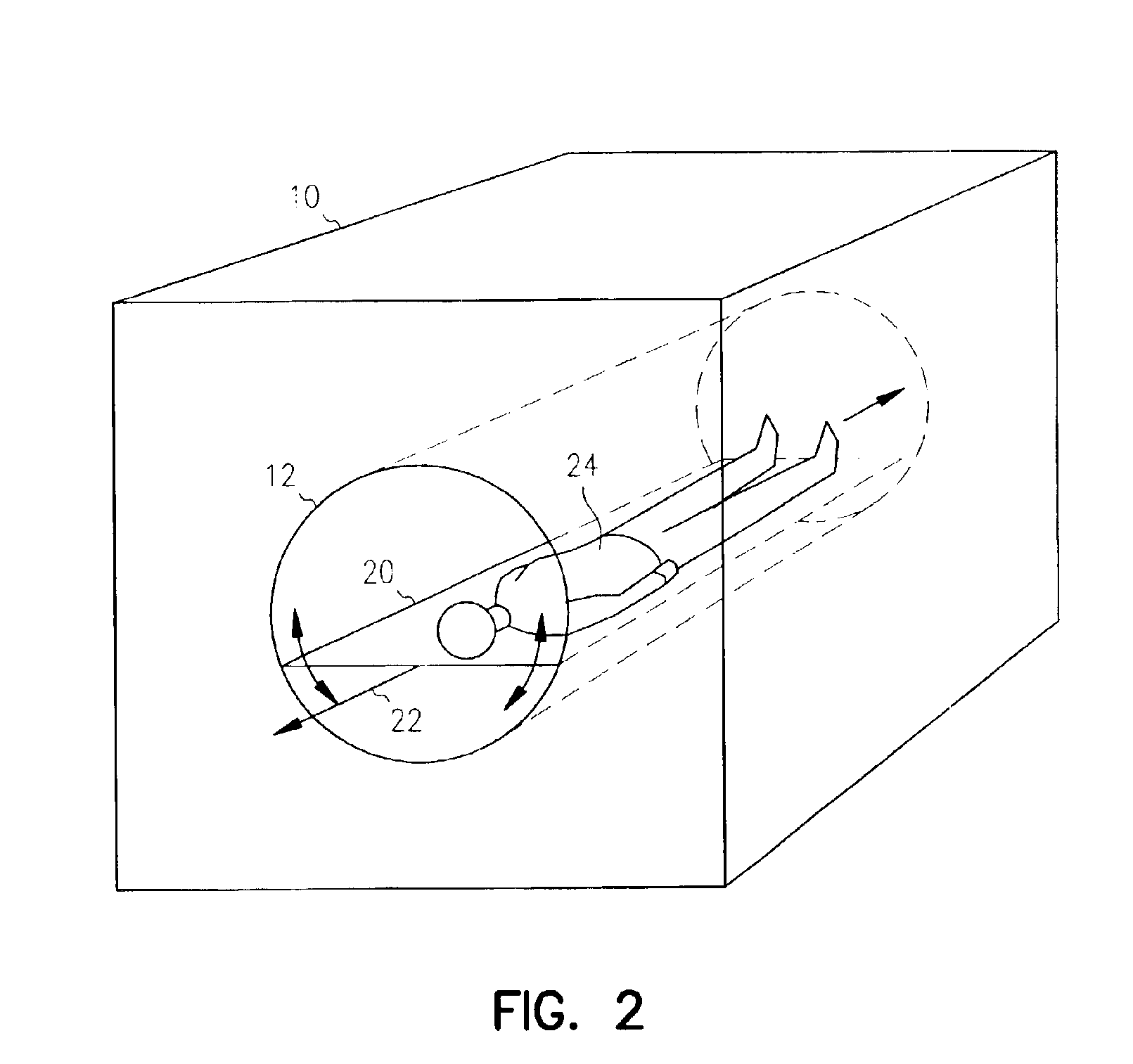
[0026]Referring now to FIG. 2, there is illustrated a method and apparatus according to the present invention. According to this embodiment, a patient's body 24 is supported on the elongate member 20 with a substantially planar surface, with the elongate member 20 having a longitudinal axis 22. The member 20 is positioned inside the bore 12 of MR scanner 10 so that at least a portion of the patient's body 24 is inside the bore 12. The member 20 is rotated about its longitudinal axis while the member is inside the bore 12, so that the patient's body 24 is rotated about the body's longitudinal axis 22 while in the bore 12 of the MR scanner. According to one embodiment, the member 20 is supported in the bore 12 on a mechanism (not shown) that supports the member 20 for rotation about the longitudinal axis 22. Such support may be provided on the edges of the member 20 or along one or more points across the center. Further, the member 20 is freely detachable from the mechanism and remova...

second embodiment

[0027]Referring now to FIG. 3, there is illustrated a method and apparatus according to the present invention. According to this embodiment a patient's body is supported on an elongate member 30 with a substantially planar surface, the elongate member 30 having a longitudinal axis and a recess 32 on one end substantially underneath a patient's head and neck when lying on the table, and including a surgical head-holder 34 supporting the patient's head above or within the recess 32. The member 30 is positioned inside a bore 12 of a MR scanner 10 so that at least a portion of the patient's body is inside the bore 12. The member 30 is freely detachable from the mechanism and removable from the bore 12.

[0028]Referring now to FIG. 4, there is illustrated yet another embodiment of a method and apparatus according to the present invention. A patient's body 44 is supported on an elongate member 40 with a substantially planar surface, the elongate member 40 having a longitudinal axis 42. The ...


PUM


Abstract

There is described method and apparatus for supporting a patient's body in a MR scanner, including supporting it to rotate about its longitudinal axis and cant about a point on the longitudinal axis. Also provided are method and apparatus for supporting a patient's head and neck and using a surgical head-holder. Yet another embodiment of the invention provides method and apparatus for attaching first and second stirrups to a member supporting the patient. According to yet another embodiment, the invention provides for keeping two or more different members for supporting a patient's body during a medical procedure conducted in conjunction with an MR scanner, wherein each member is adapted to be detachably inserted into a bore of the MR scanner, and wherein each member provides for a different patient support functionality, selecting one of the different members for use in a medical procedure, positioning a patient's body on the selected member, and engaging the member with the MR scanner such that the member is disposed at least in part in a bore of the scanner.

Description

RELATED APPLICATION[0001]This application is a continuation-in-part of U.S. patent application Ser. No. 09 / 849,792, filed May 4, 2001, now abandoned which claims benefit under 35 U.S.C. 119(e) from U.S. Provisional Application Ser. No. 60 / 202,358, filed May 5, 2000, which is incorporated by reference.TECHNICAL FIELD OF THE INVENTION[0002]The present invention relates generally to the field of medicine, and more particularly to MR scanning equipment and its use in medical procedures.BACKGROUND[0003]Since its development in the early 1980s, magnetic resonance (MR) imaging has become the dominant form in imaging of the central nervous systems and is continuing to grow in its uses in musculoskeletal and body imaging. It offers unprecedented abilities in visualization of the human body. Over the past few years, MR imaging has been investigated as a tool for use in association with therapy, so-called interventional MR imaging or MR-guided therapy. To accomplish this, various new scanner d...

Claims


Application Information

Patent Timeline
IPC IPC(8): A61B5/055
CPCA61B5/0555A61B5/055A61B5/704
Inventor TRUWIT, CHARLES L.
Owner RGT UNIV OF MINNESOTA
Why Eureka
Try Eureka