
Printer having a replaceable head unit and caping mechanism therefor

a printing machine and head unit technology, applied in printing and other directions, can solve the problems of insufficient purging and needing replacement of the head uni

Inactive Publication Date:
View PDF9 Cites 34 Cited by
  • Summary
  • Abstract
  • Description
  • Claims
  • Application Information

AI Technical Summary

Benefits of technology

As stated above, the protective cap of this printer is supported in such a manner that, while it is out of contact with the ejection face, that is to say, while the head holder is not mounted on the carriage, the cap is oriented opposite the direction in which the head holder can be moved toward the turning axis. For replacement of the print head, a new head holder holding a new print head is first moved to the turning axis until part of the holder engages with the carriage. When the holder part engages with the carriage, the ejection face of this head faces and comes into close contact with the cap, as shown in FIG. 9B of the accompanying drawings. Subsequently, while the head holder is turned around the axis, the protective cap is turned, kept in contact with the ejection face. Therefore, while the head holder is turned, the protective cap does not slide on the ejection face. This prevents the nozzle from clogging due to the cap slide or slip.
While the head holder of this printer is turning around the turning axis, the protective cap can move from the first position to the second position, kept in close contact with the ejection face of the print head. That is to say, while the cap is moving from the first position to the second position, it does not slide on the ejection face. This prevents the nozzle from clogging due to the cap slide.
While the print head of this printer is replaced, the protective cap does not slide on the ejection face of the head. This prevents the nozzle from clogging.

Problems solved by technology

There may be cases where the heads need to be replaced because of their lives, trouble, etc.
There may be cases where such purging is not sufficient to remove dust etc.

Method used


Image

  • Printer having a replaceable head unit and caping mechanism therefor
  • Printer having a replaceable head unit and caping mechanism therefor
  • Printer having a replaceable head unit and caping mechanism therefor

Examples


Embodiment Construction

In the drawing figures for the embodiments of the invention, like parts are accorded the same reference numerals.

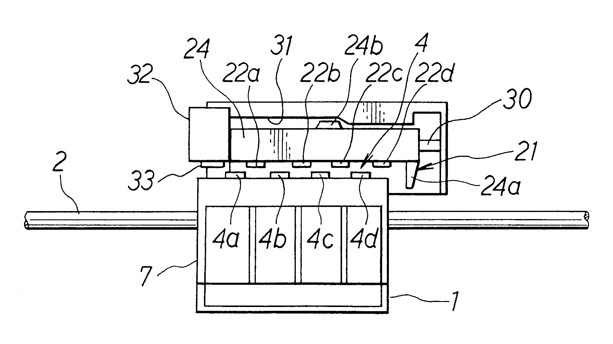
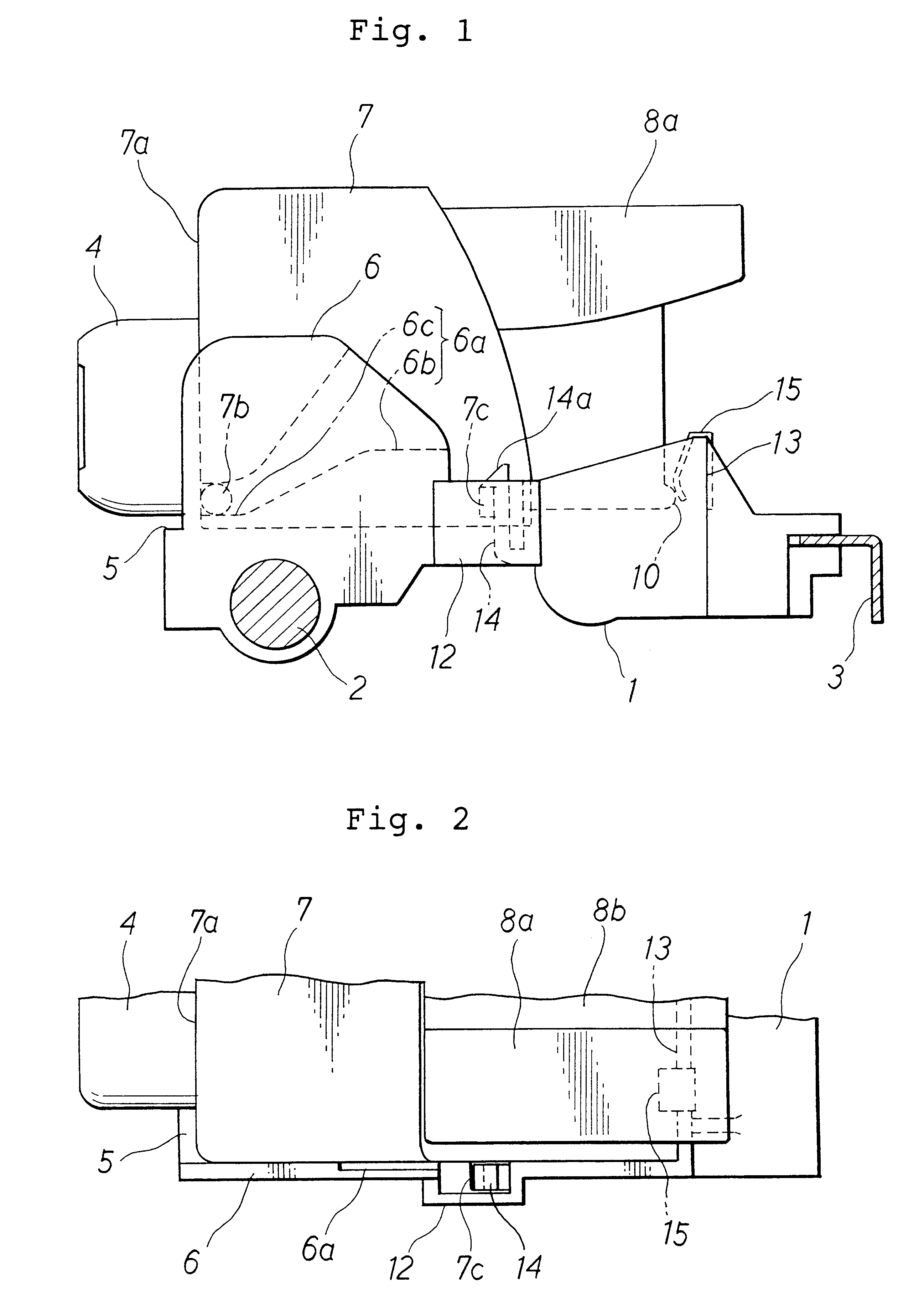
With reference to FIG. 1, an ink jet color printer embodying the invention includes a guide rod 2 and a guide bar 3, which extend horizontally in parallel. A carriage 1 is supported slidably on the rod 2 and the bar 3, and can be reciprocated along them by a known driving means. The driving means includes a timing belt (not shown), which can be driven by a carriage motor 74 (FIG. 8). With reference to FIGS. 1 and 2, a head holder 7 can be mounted on the carriage 1. A head unit 4 is fixed to the front wall of the holder 7.

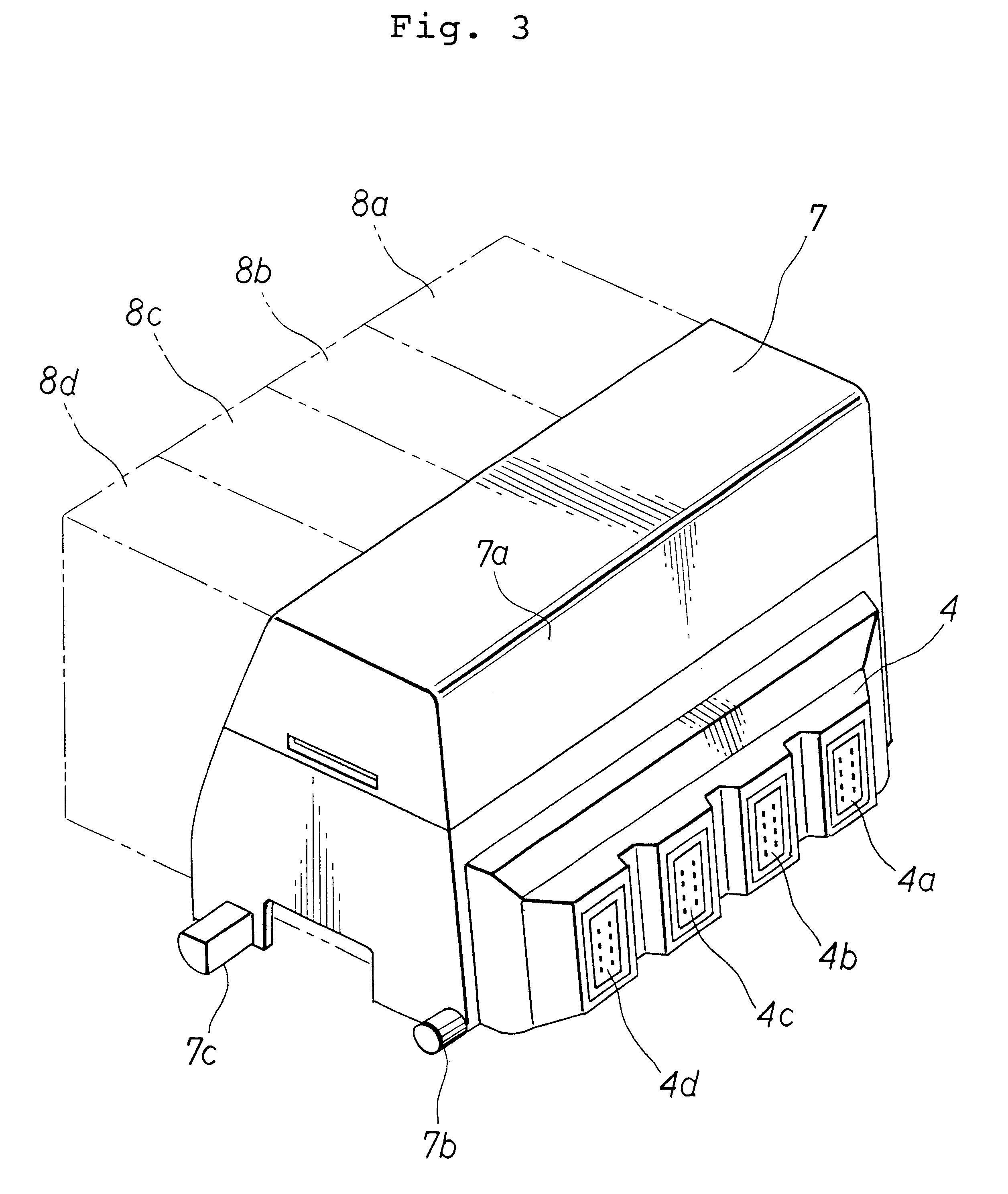
As shown in FIG. 3, the head unit 4 includes four print heads 4a, 4b, 4c and 4d for different colors. Each of the heads 4a-4d has an ejection face and an array of nozzles formed in it. The front ends of the nozzles are open in the ejection face. The heads 4a-4d can be supplied with ink from four ink cartridges 8a, 8b, 8c and 8d, respectively. Printing pap...


PUM


Abstract

An ink jet printer incudes a carriage supported slidably in opposite reciprocating directions and having a turning axis which extends in these directions. The printer also includes a head holder a and a head unit. The unit is fixed to the front wall of the holder, and has print heads. The printer further includes protective caps for covering the ejection faces of the heads respectively. When the heads are replaced at their position where their ejection faces are opposite the caps the caps are oriented opposite the direction in which the holder is moved toward the axis. When the holder is put on the carriage in such a direction that the holder approaches the caps the caps cap the heads. The caps can move in the directions in which the holder turn. After part of the holder is put on the carriage, the holder is turned around the axis to its normal position, where the heads correctly face the printing position on printing paper. The holder turns together with the caps with the heads capped with them. The cap does not rub on the ejection faces of the heads.

Description

BACKGROUND OF THE INVENTION1. Field of the InventionThe present invention relates to an ink jet printer having an exchangable printing head.2. Description of Related ArtA known ink jet printer includes a carriage, which can reciprocate horizontally along a printing medium. A head holder is mounted removably on the carriage, and supports print heads on it. The heads can eject ink onto the medium. The printer also includes a capping device, which includes protective caps for covering the ejection faces of the heads to prevent the ink on and in the heads from drying. There may be cases where the heads need to be replaced because of their lives, trouble, etc.FIGS. 20, 21A, 21B, 21C, 22A and 22B of the accompanying drawings show a known ink jet printer of the foregoing type. As shown in FIG. 20, the printer includes a carriage 103, a head holder 102 mounted removably on the carriage 103, and print heads 101 (only one shown) supported on the holder 102. Each head 101 has an ejection face ...

Claims


Application Information

Patent Timeline
Patent Type & Authority Patents(United States)
IPC IPC(8): B41J2/165B41J2/01
CPCB41J2/16511B41J2002/16576
Inventor IMAI, KOJI
Learn More