Terminal structure of switch

a terminal structure and switch technology, applied in the direction of switch terminal/connection, snap-action arrangement, coupling device connection, etc., can solve the problems of narrow width v.sub.2 of the space for inserting a wire therein, and the inability to insert and connect thick wires from the outsid

Inactive Publication Date: 2001-07-03
FUJI ELECTRIC FA COMPONENTS & SYST CO LTD
View PDF6 Cites 5 Cited by
  • Summary
  • Abstract
  • Description
  • Claims
  • Application Information

AI Technical Summary

Problems solved by technology

(1) According to the conventional switch, there has such a structure that the partition walls 3a elected upward from the intermediate cover 3 are respectively formed so as to surround the corresponding terminal conductors 14 drawn to the terminal portion for the respective phases and the upper cover 2 is fitted to the partition walls 3a from the outside. Accordingly, a space for inserting the wires into the terminal portion from the outside is limited by the partition walls. That is, the thickness of the side walls 2a and the partition walls 3a is required to be larger to some extent in order to secure the mechanical strength of the upper cover 2 and the int

Method used


Image

  • Terminal structure of switch
  • Terminal structure of switch
  • Terminal structure of switch

Examples


Embodiment Construction

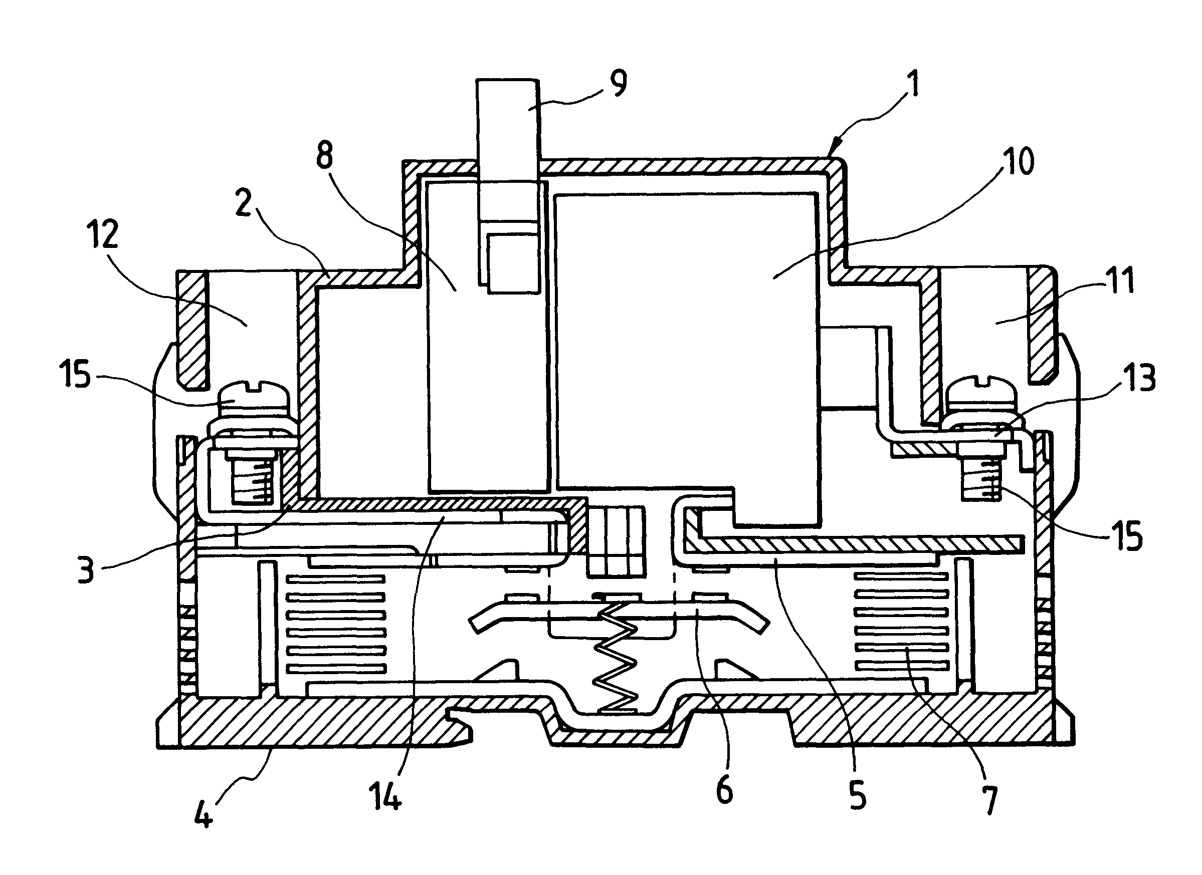
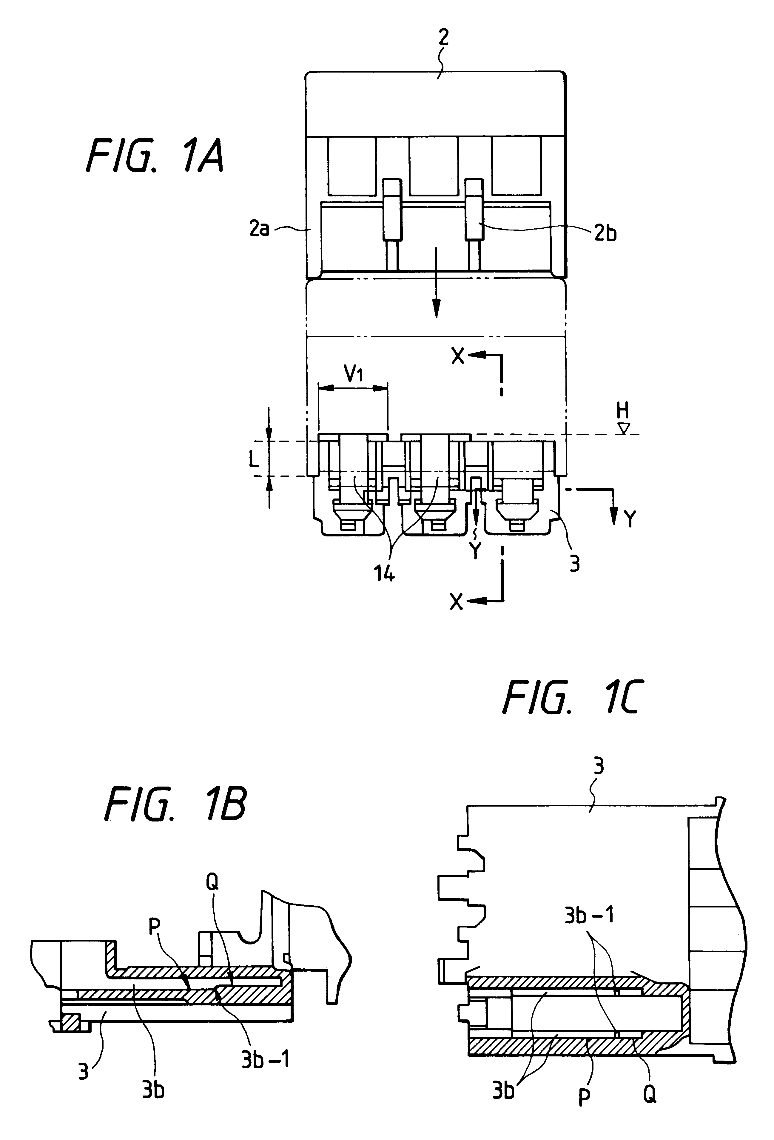
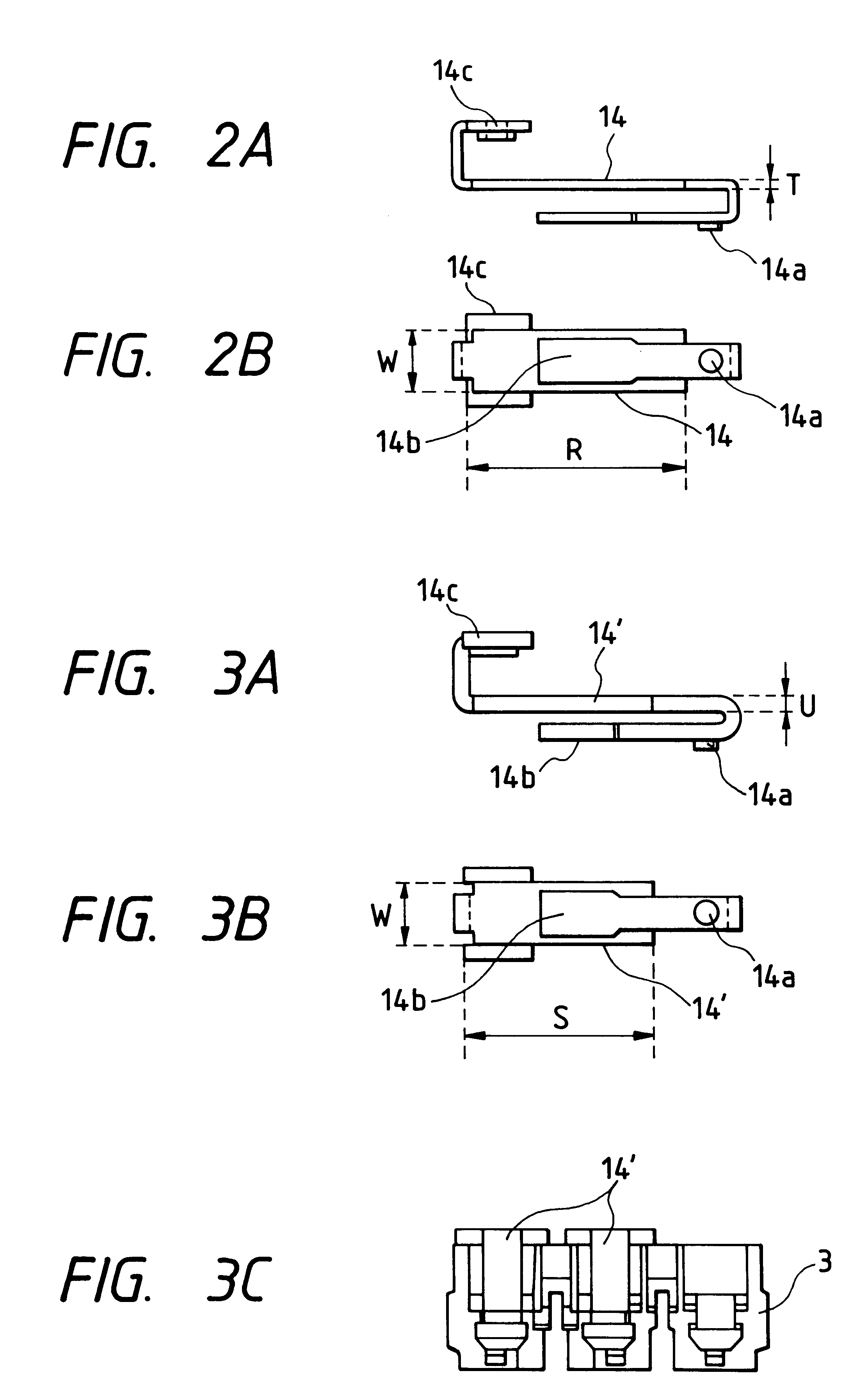
The embodiment of the present invention will be explained with reference to FIGS. 1A to 3C. In the figures showing the embodiment, like parts corresponding to those of FIGS. 4 and 5A and 5B are marked with the same references and the explanation thereof is omitted

First, in FIGS. 1A to 1C, the terminal portion of an intermediate cover 3 holding terminal conductors 14 is configured in a manner that an upper surface of the intermediate cover 3 is flat and no partition wall 3a elected from the intermediate cover 3 as shown in FIG. 5 is formed. Inter-phase partition walls 2b for the respective phases are formed only on an upper cover 2 side so as to surround the terminal conductors 14 and terminal screws 15 in combination with side walls 2a. In an assembled state where the upper cover 2 is fitted on the intermediate cover 3 as shown by a dotted line in FIG. 1A, the terminal portion is set in a manner that the left and right side surfaces of the intermediate cover 3 fit to the left and ri...


PUM


Abstract

In a terminal structure of a switch which is arranged in a manner that a terminal conductor 14 with a terminal screw drawn from the inner portion of the casing is disposed at every phase in the terminal portion of a casing formed by the three-divided structure of an upper cover 2, an intermediate cover 3 and a lower cover, and wires inserted into the terminal portion from the outside are respectively fastened by the screws to be coupled to the terminal conductors, the terminal conductors of the respective phases are pressed into the terminal fixing grooves 3b formed at the intermediate cover and fixed to the casing in a manner that the left and right side edges of each of the terminal conductors are pressed into the grooves. The terminal conductor of each phase is surrounded by a side wall 2a and an inter-phase partition wall 2b formed at the upper cover, and the fitting portion of the upper cover and the intermediate cover is defined at a portion lower than the terminal conductors thereby to enlarge the width of a space into which wires are inserted. Further, step portions 3b-1 are formed at portions of the terminal fixing grooves so that two kinds of terminal conductors having different plate thickness can be selectively assembled in the intermediate cover.

Description

1. Field of the InventionThe present invention relates to a terminal structure of a switch to be applied to a molded case circuit breaker, an electromagnetic contactor etc.2. Description of the Related ArtThe assembled structure of a conventional switch (for three-phase) which is applied to the aforesaid molded case circuit breaker is shown in FIG. 4. In the figure, a reference numeral 1 denotes a casing (resin casing) of three-divided structure formed by combining an upper cover 2, an intermediate cover 3 and a lower cover 4 in a fitting manner. A reference numeral 5 denotes a fixed contact shoe incorporated in the breaker portion of the casing 1, 6 a movablecontact shoe, 7 an arc-extinguishing plate, 8 a switching mechanism, 9 an operation handle and 10 an over current tripping device. A terminal portion 11 on power supply side and a terminal portion 12 on load side are formed at the front end and the rear end of the casing 1, respectively. The terminal portions 11 and 12 are prov...

Claims


Application Information

Patent Timeline
IPC IPC(8): H01H71/02H01H71/08H01H73/20
CPCH01H71/08H01H71/025
Inventor KAWATA, HISAOUCHIDA, NAOSHIKUBOYAMA, KATSUNORITAKAHASHI, TATSUNORI
Owner FUJI ELECTRIC FA COMPONENTS & SYST CO LTD
Why Eureka
Try Eureka