Vertically oriented apparatus for bending tubing, and method of using same

a vertical orientation and tubing technology, applied in the field of automatic bending, can solve the problem of relatively high cos

Inactive Publication Date: 2001-07-17
ADAPTIVE MOTION CONTROL SYST
View PDF18 Cites 18 Cited by
  • Summary
  • Abstract
  • Description
  • Claims
  • Application Information

AI Technical Summary

Problems solved by technology

This conventional arrangement of the machine takes up a large floor space in a manufacturing facility, which tends to be relatively expensive.

Method used


Image

  • Vertically oriented apparatus for bending tubing, and method of using same
  • Vertically oriented apparatus for bending tubing, and method of using same
  • Vertically oriented apparatus for bending tubing, and method of using same

Examples


Embodiment Construction

Overview

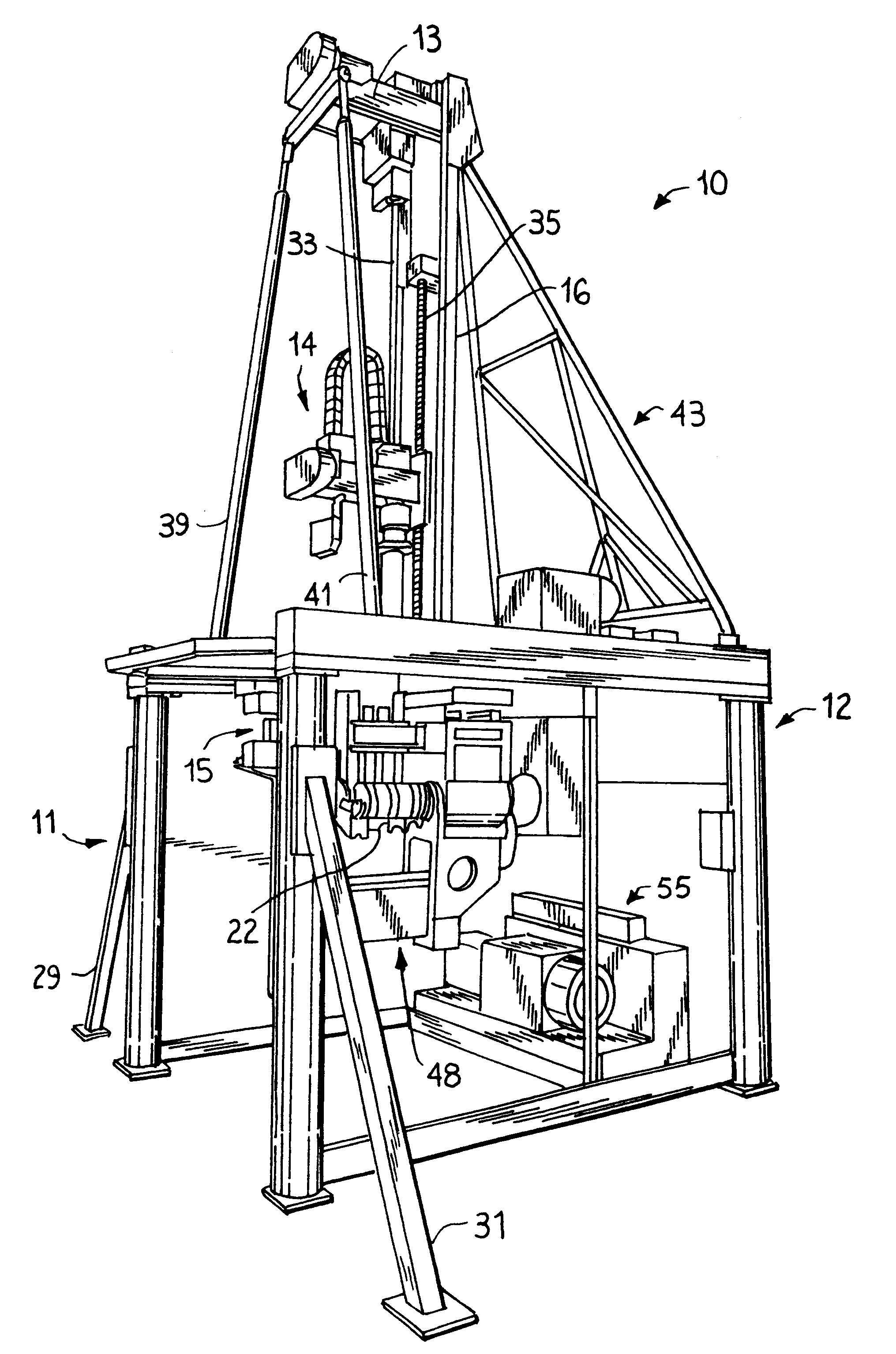
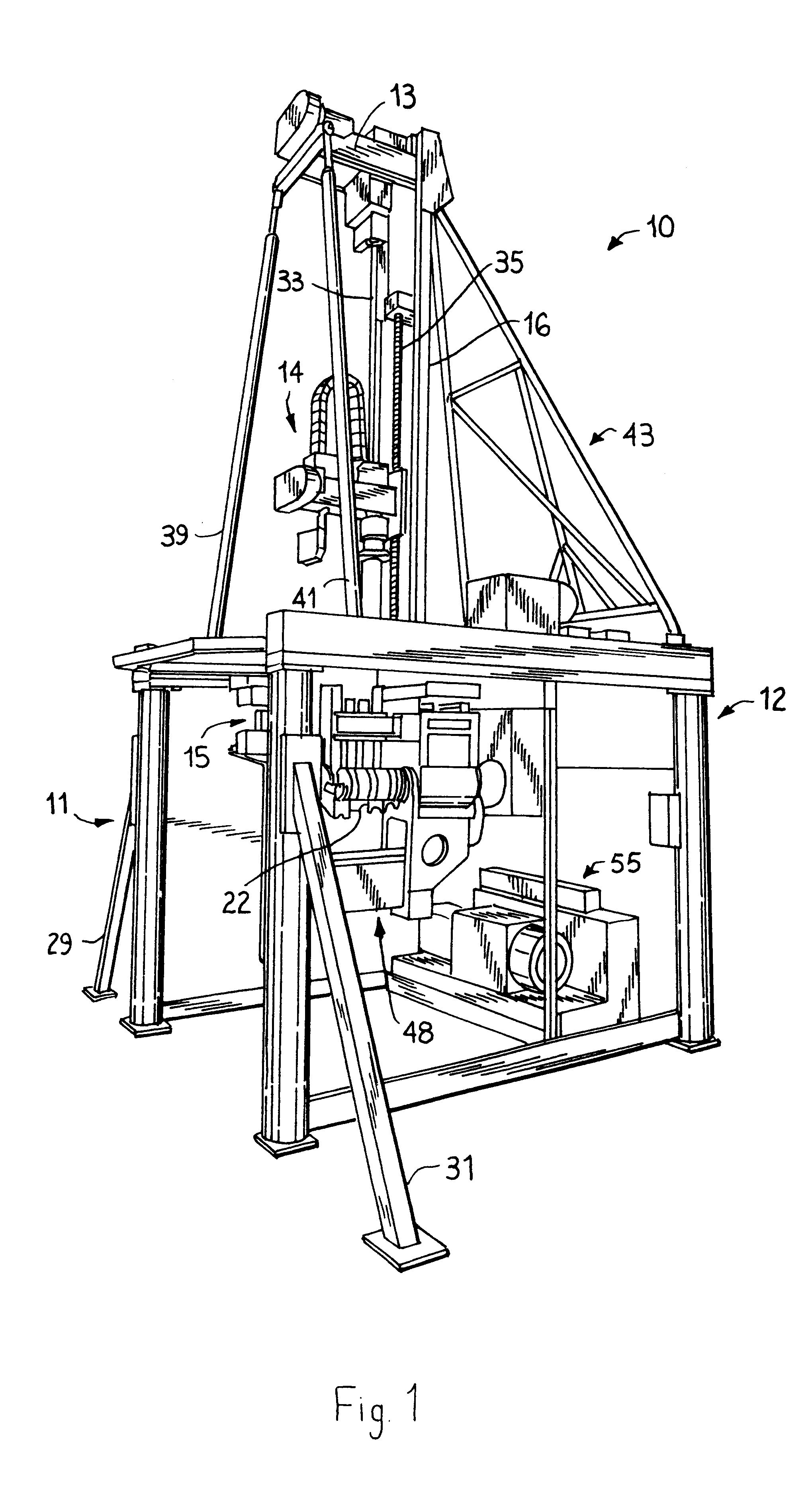
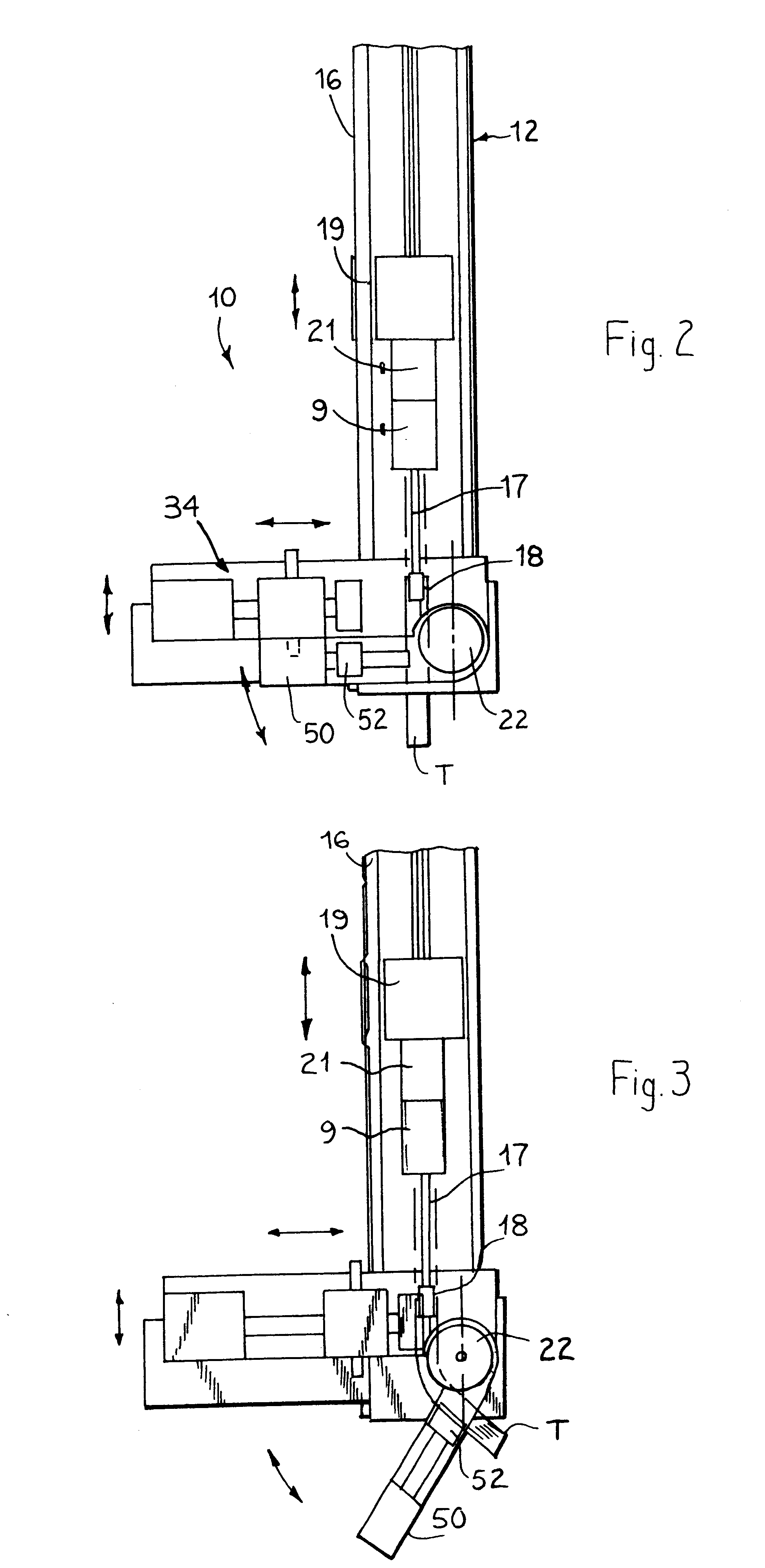
Referring now to the drawings, and particularly to FIGS. 1-3 thereof, a vertically oriented apparatus for bending and cutting tubing is shown generally at 10. The apparatus 10 includes a support frame 12 and a tubing advance mechanism 14, attached to the support frame, for advancing a tubing workpiece T therealong. Other components of the apparatus include a bend die 22, a pressure die assembly 34 (FIG. 2), a bend arm assembly 48, a cutter mechanism 15, and a programmable electronic controller 23 (FIG. 9). Each of these components and subassemblies will be discussed in further detail below.

The Support Frame and Tubing Advance Mechanism

The support frame 12 includes a number of different pieces, and is preferably made of a strong metal such as cast iron or steel. As best seen in FIG. 1, the support frame 12 includes a roughly cube-shaped cage 11 reinforced by opposed support braces 29, 31, disposed at an angle of approximately 45 degrees with respect to the vertical, as shown....


PUM

PropertyMeasurementUnit
angleaaaaaaaaaa
lengthaaaaaaaaaa
widthaaaaaaaaaa

Abstract

A vertically oriented tube bending apparatus includes a vertically oriented support frame, which takes up less floor space than the previously known tubing benders. A tube bending apparatus in accordance with the invention, generally, includes a support frame having a length, a width, and a height, wherein the greatest of these is the height. The apparatus further includes a tubing advance mechanism, attached to the support frame, for advancing a tubing workpiece along a substantially vertical path. A bend die is also provided which is rotatably attached to the support frame and pivotally movable about a pivot axis. The bend die has an outer side edge with an arcuate peripheral groove formed therein to receive a portion of a tubing workpiece. The apparatus also includes a pressure die movably attached to said support frame. The pressure die has a reciprocally movable first pressure applicator for applying pressure to a follower slide; and a follower slide which is slidably attached to said first pressure applicator. The follower slide includes an inner face having an arcuate cutout channel formed therein to receive a portion of a tubing workpiece therein substantially opposite the bend die. The apparatus also includes a bend arm assembly for bending a tubing workpiece against the bend die. The bend arm assembly is rotatably movable about the pivot axis of the bend die. The invention also encompasses a method of using the vertically oriented tubing bender to bend a piece of tubing stock.

Description

1. Field of the InventionThe present invention relates to a vertically oriented apparatus for bending metal tubing. More particularly, the present invention relates to an automated and computer controlled apparatus for bending tubing, in which the height of the apparatus is greater than the width thereof, in order to occupy less floor space than is required for a conventional tube bending machine, and in which tubing stock is moved along a substantially vertical path.2. Description of the Background ArtMany different types of tube bending machines are known and commercially available. Some examples of tubing benders may be found in U.S. Pat. Nos. 3,724,256, 4,126,030, 4,606,250, 4,703,678 and 5,025,651.However, it is believed that all of the known tubing benders are mounted on a horizontally oriented support frame or base, and move a piece of tubing stock therethrough along a substantially horizontal path. This conventional arrangement of the machine takes up a large floor space in ...

Claims


Application Information

Patent Timeline
Patent Type & Authority Patents(United States)
IPC IPC(8): B21D7/00B21D7/024B21D7/12B21D7/02B23D31/00B23D21/00
CPCB21D7/024B23D31/00B23D21/00B21D7/12
Inventor WEBSTER, M. CRAIG
Owner ADAPTIVE MOTION CONTROL SYST
Why Eureka
Try Eureka