Tube bottom sensing for small fluid samples

a technology of fluid sample and tube bottom, which is applied in the field of small fluid sample sensing methods and apparatuses, can solve the problems of dead volume of sample, which is unavailable for testing, and achieves the effect of improving the accuracy of sample sampling

Inactive Publication Date: 2001-08-07
SIEMENS HEALTHCARE DIAGNOSTICS INC
View PDF27 Cites 94 Cited by
  • Summary
  • Abstract
  • Description
  • Claims
  • Application Information

AI Technical Summary

Problems solved by technology

However, to ensure that an insufficient volume of sample will not be drawn, owing to the sample level being too close to the bottom of the tube, the pipette tip will only be allowed to be lowered to a certain level within the tube resulting in a volume of sample, called the dead volume, that is unavailable for testing.

Method used


Image

  • Tube bottom sensing for small fluid samples
  • Tube bottom sensing for small fluid samples
  • Tube bottom sensing for small fluid samples

Examples


Embodiment Construction

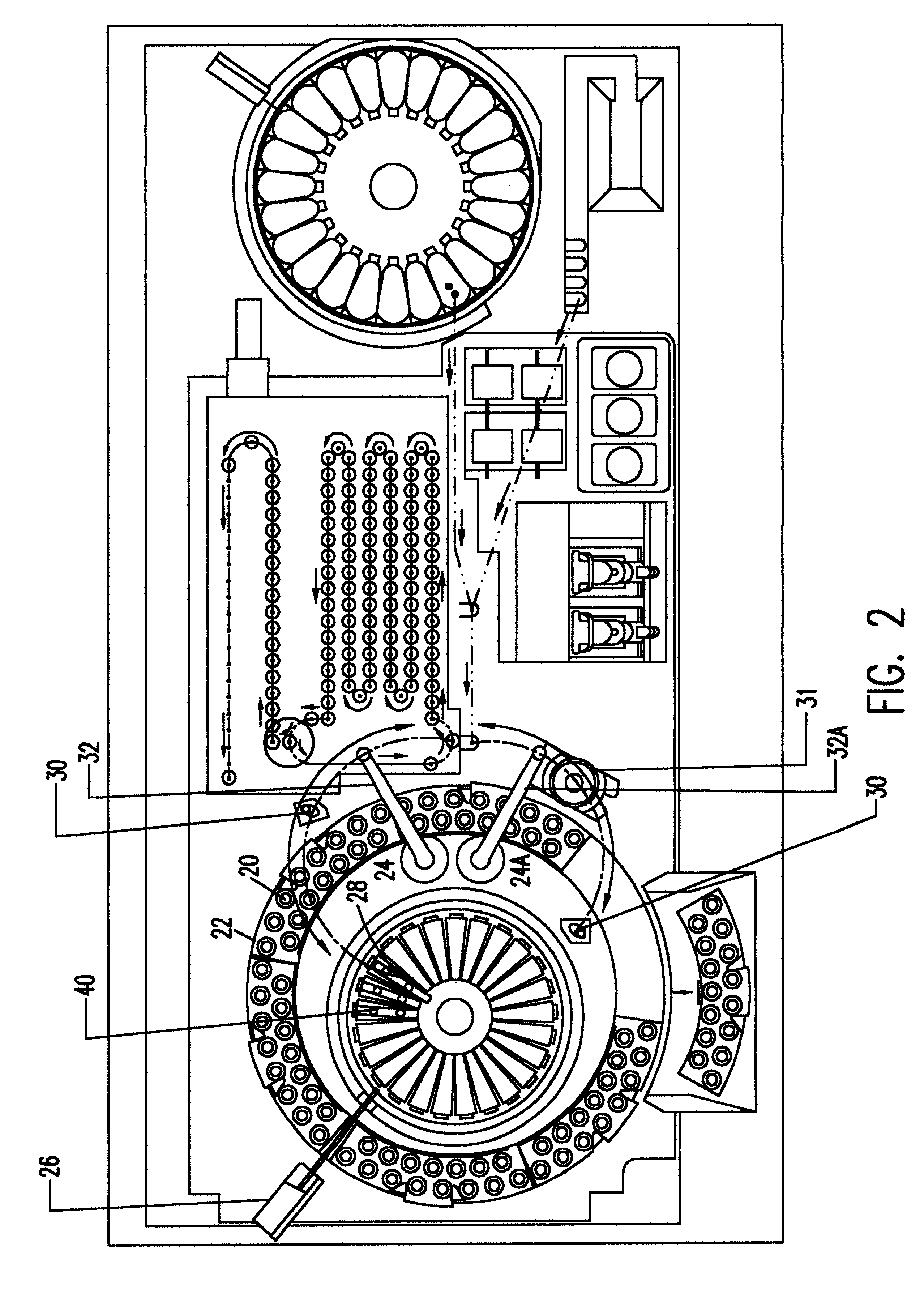
The present invention is directed to a method and apparatus for sensing fluids of small samples in a tube and, more specifically, to a method and apparatus for determining the volume of a fluid in a tube that is below a near bottom tube level using a bottom sensing device. The bottom sensing device is used to determine the volume of a fluid in a tube, as described in detail below. By using the apparatus and method of the present invention, a pipetting station of an automatic analyzer or other device may aspirate fluids of small samples for testing thereon.

In order to accomplish the objectives of the present invention, a bottom sensing device is implemented in conjunction with a pipetting tip having a capacitive level sensor or other means of sensing fluid levels. A pipetting capacitive level sensor contemplated for use with the present invention is disclosed in U.S. Pat. No. 5,648,727 and is incorporated herein by reference in its entirety. In general, the capacitive level sensor di...


PUM

PropertyMeasurementUnit
distanceaaaaaaaaaa
distanceaaaaaaaaaa
volumeaaaaaaaaaa

Abstract

A pipetting station having a bottom sensing device is provided in conjunction with one of any known liquid level sensing devices. The bottom sensing device includes a pipetting probe spring mounted to a pipetting arm of the pipetting station. The bottom sensing device also includes a sensor for determining when a pipetting tip of the pipetting probe is in contact with a bottom of a tube. The bottom sensing device permits the pipetting probe to measure an exact volume of fluid in the tube by allowing the pipetting tip to be lowered to the bottom of the tube beyond the sensed fluid level.

Description

1. Field of the InventionThe present invention generally relates to a method and apparatus for sensing small fluid samples in a vessel and, more particularly, to a method and apparatus for determining the volume of a fluid in a vessel, such as a test tube, using a bottom sensing device (e.g., tip jam device).2. Background DescriptionAnalyses of fluids, especially bodily fluids such as urine and blood, are important to the diagnoses and treatment of various illness and other conditions. These illnesses and conditions can range from various forms of cancers to blood diseases to drug use and others.In order to analyze a bodily fluid, a sample of fluid is first taken from a person and analyzed either by hand or by an automatic analyzer or other device of the type well known in the art. In the case of an automatic analyzer, for example, the bodily fluid is disposed in a tube which, in turn, is disposed on a carousel or other conveying mechanism. The carousel or other conveying mechanism ...

Claims


Application Information

Patent Timeline
Patent Type & Authority Patents(United States)
IPC IPC(8): G01N35/10
CPCG01N35/1011Y10T436/119163Y10T436/2575Y10T436/115831Y10T436/12
Inventor TYBERG, WILLIAMBABSON, ARTHUR L.
Owner SIEMENS HEALTHCARE DIAGNOSTICS INC
Why Eureka
Try Eureka