Apparatus for inverting containers

a container and apparatus technology, applied in the field of apparatus for inverting containers, can solve the problems of labour and/or time-consuming discharge methods of containers with a bottom discharge incorporated in the base or pallet forming part of containers, and have not found favour with users

Inactive Publication Date: 2001-08-14
KARPISEK LADISLAV STEPHAN
View PDF11 Cites 13 Cited by
  • Summary
  • Abstract
  • Description
  • Claims
  • Application Information

AI Technical Summary

Problems solved by technology

For a number of reasons containers with a bottom discharge incorporated in the base or pallet forming part of the container have not found favour with users.
This discharge method is labour and/or ti

Method used


Image

  • Apparatus for inverting containers
  • Apparatus for inverting containers
  • Apparatus for inverting containers

Examples


Embodiment Construction

.

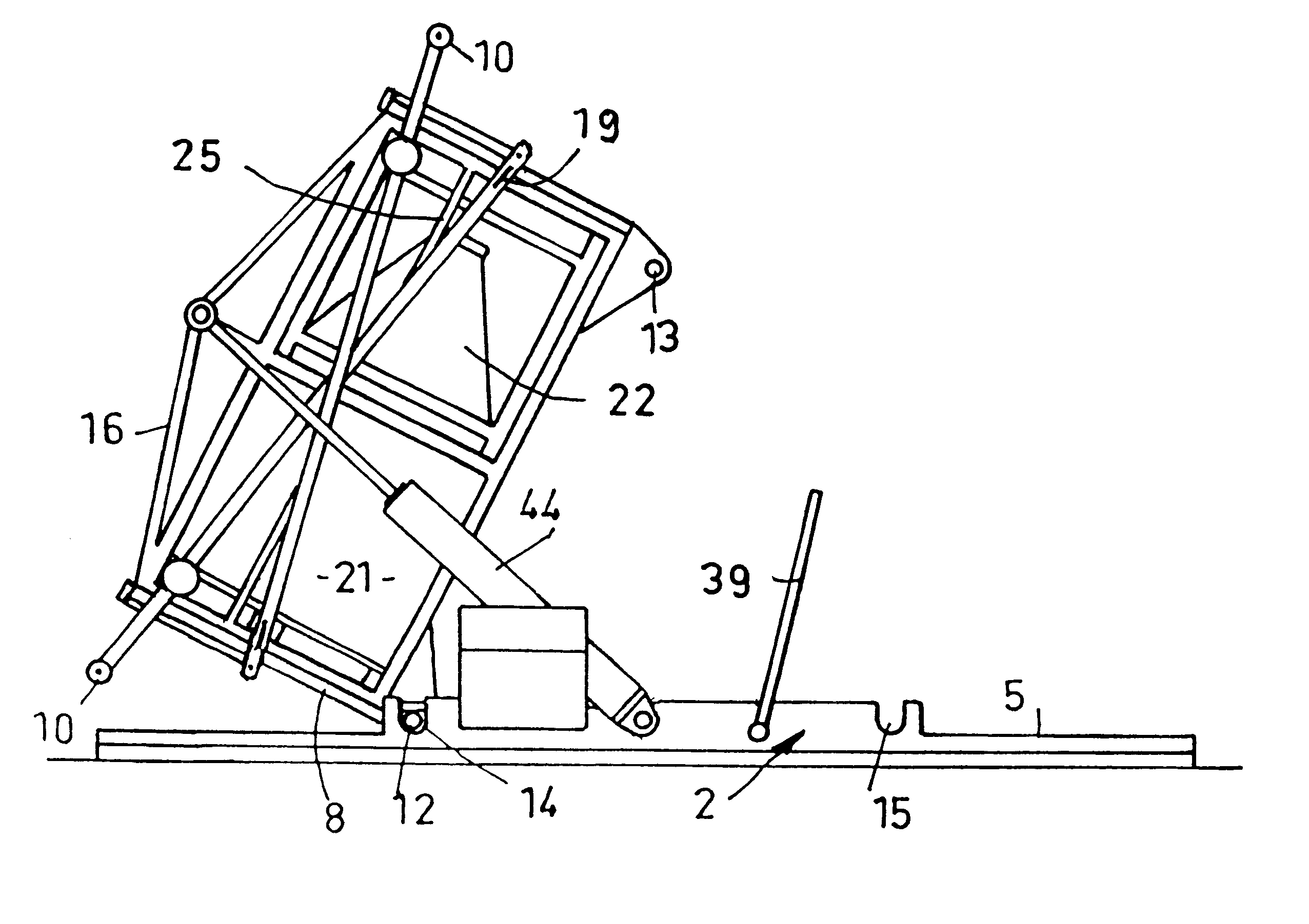
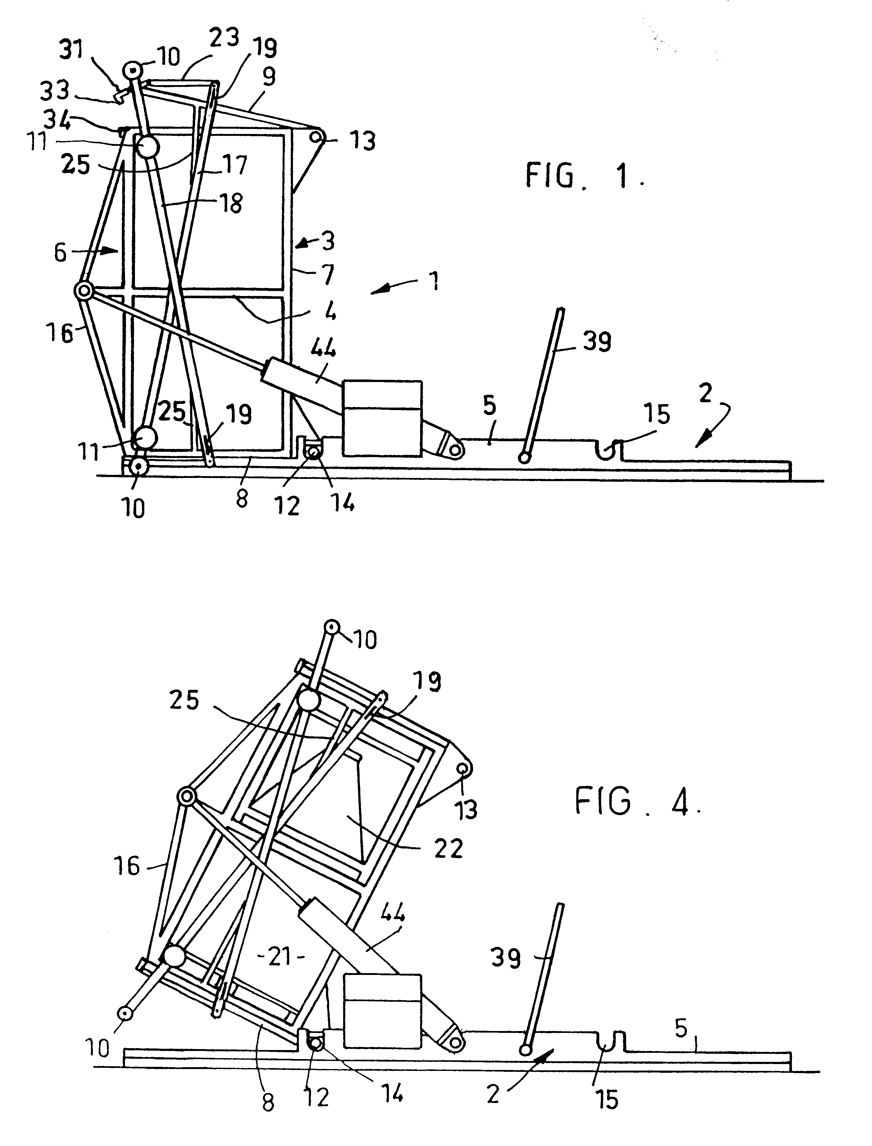
The illustrated turn-over apparatus, indicated generally as 1, includes a base 2 with a container support cradle indicated generally 3, hereinafter for convenience simply referred to as the cradle. The cradle 3 includes a skeletal frame of welded metal bars and with two side frames parts 4, an open front side 6 and a back part 7 and it has two end covers 8 and 9 pivotally connected to the skeletal frame at locations identified 12 and 13 respectively, which also indicate pivot pins extending from lugs on the skeletal frame. Alternatively, there can be a rod extending across the frame and projecting from both sides to provide the pivot pins.

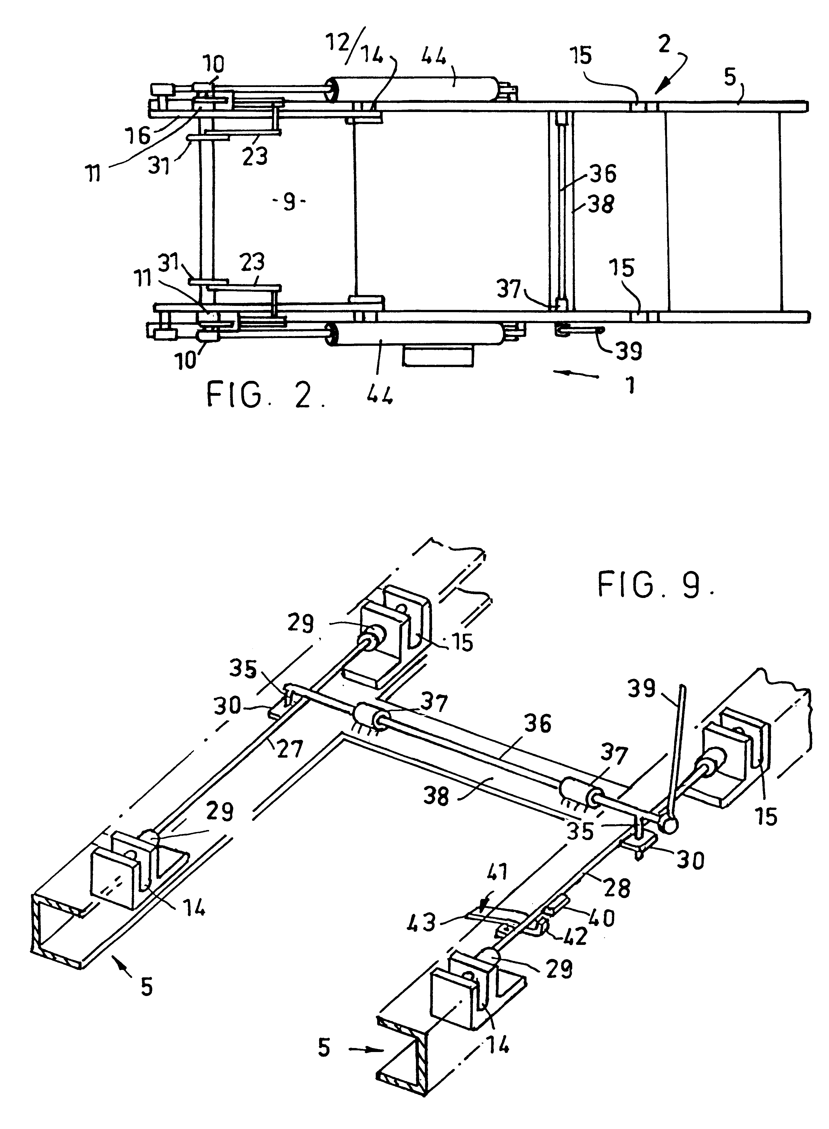
The base 2 includes two laterally spaced rails 5 of channel form to house operating mechanisms to be described. There are laterally aligned socket pairs 14 and 15 in the rails 5. The socket pairs 14,15 are engagable by the pin pairs 12,13 as the cradle executes an end over end inversion.

As illustrated in FIG. 1 the cradle 3 is resting on the end c...


PUM


Abstract

A container turn-over apparatus (1) including a base (2) and a container cradled (3) with openable latchable ends (8,9) and an open side (6) to allow a container to be placed in the cradle (3). Two selectively engagable spaced apart pivotal connections (12,14 & 13,15) allow the cradle (3) to be turned end over by means of piston and cylinder assemblies (44). When the cradle (3) is turned over to stand on one of its ends (8,9) the other end of the cradle (3) is automatically unlatched and opened.

Description

This invention is concerned generally with apparatus to invert an open topped container to allow the container to be discharged through the open top.BACKGROUND TO THE INVENTIONWhilst the invention has been devised with containers in mind which are of the type which comprise a pallet or base to which there is mounted four interlocked sides the invention is not limited to such containers.When containers are to be emptied the methods adopted depend to a large extent on the contents of the container. In the case of flowable material, such as granules, gravitational discharge is the preferred method. To facilitate this method of emptying a container attempts have been made to develop containers which have bottom discharge means. For a number of reasons containers with a bottom discharge incorporated in the base or pallet forming part of the container have not found favour with users.An alternative is to tilt the container, usually in a tilting device on which the container is mounted, to...

Claims


Application Information

Patent Timeline
IPC IPC(8): B65G65/00B65G65/23
CPCB65G65/23
Inventor KARPISEK, LADISLAV STEPHAN
Owner KARPISEK LADISLAV STEPHAN
Why Eureka
Try Eureka