Machine tool clamping device

a technology of clamping device and machine tool, which is applied in the direction of attaching milling device, manufacturing tools, mechanical equipment, etc., can solve the problems of reducing the efficiency of tool changing operation, unable to command the draw bar to move, and wasting tim

Inactive Publication Date: 2001-09-11
SODICK CO LTD
View PDF12 Cites 42 Cited by
  • Summary
  • Abstract
  • Description
  • Claims
  • Application Information

AI Technical Summary

Problems solved by technology

However, a machine tool controller of this type cannot command the draw bar to move until a confirmation signal has been received.
This wait time reduces tool changing operation efficiency.

Method used


Image

  • Machine tool clamping device
  • Machine tool clamping device
  • Machine tool clamping device

Examples


Embodiment Construction

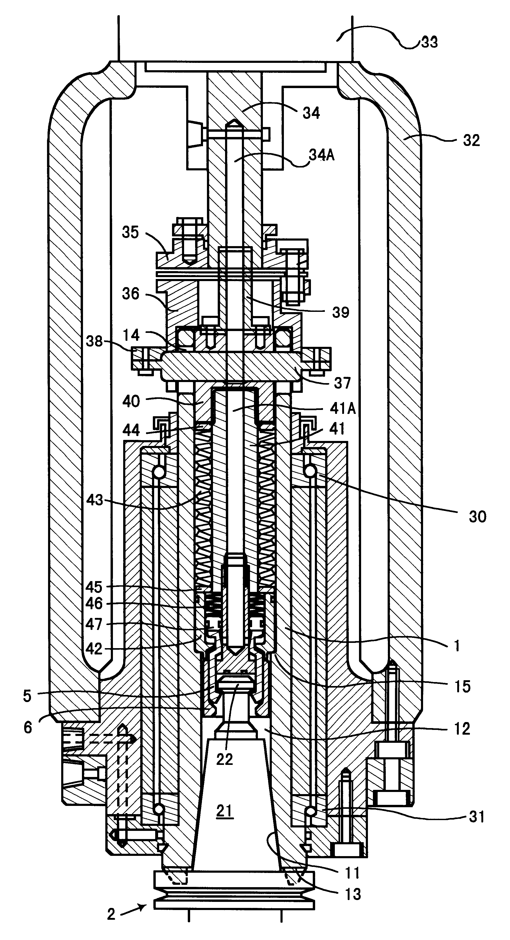
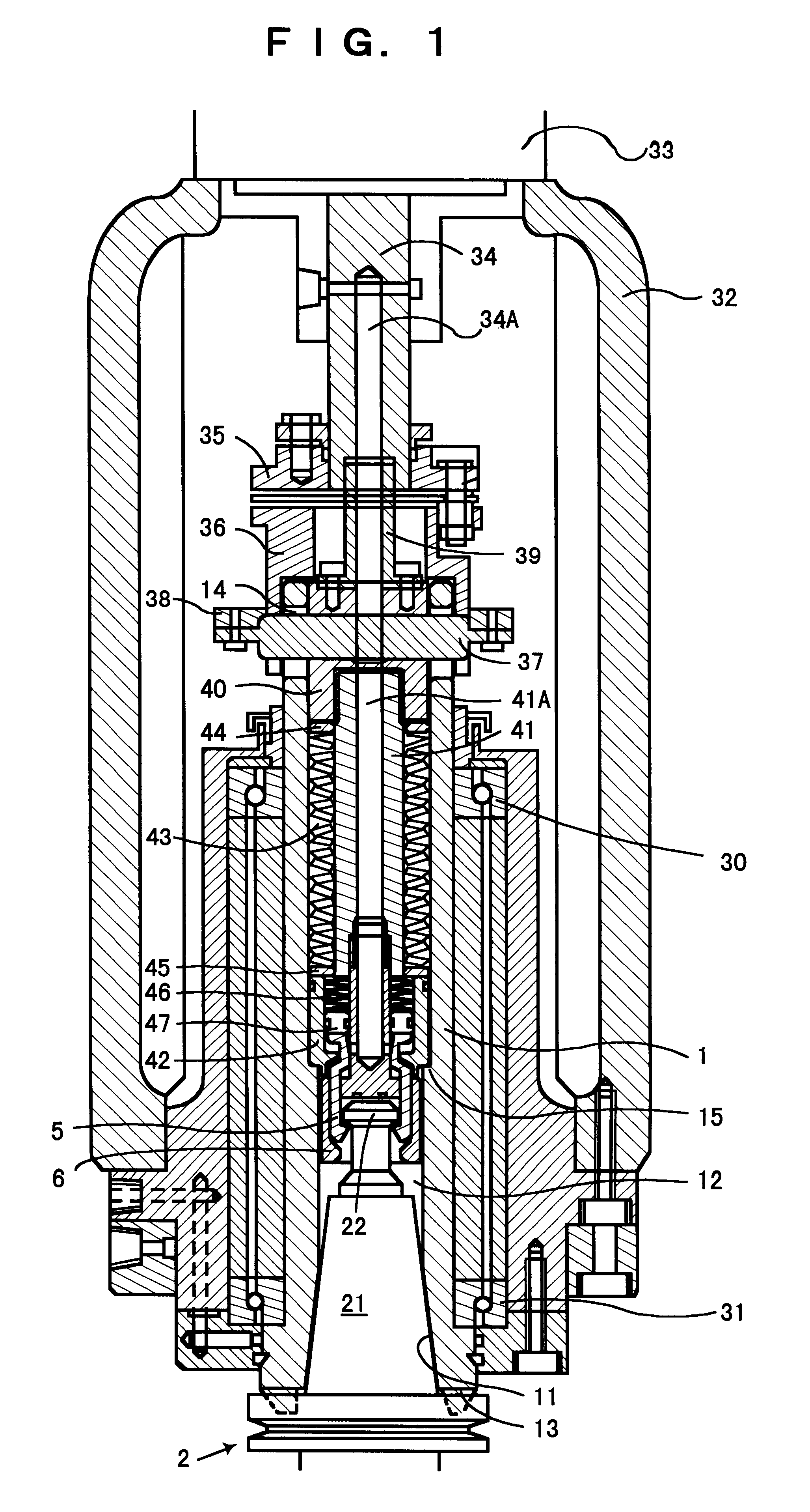
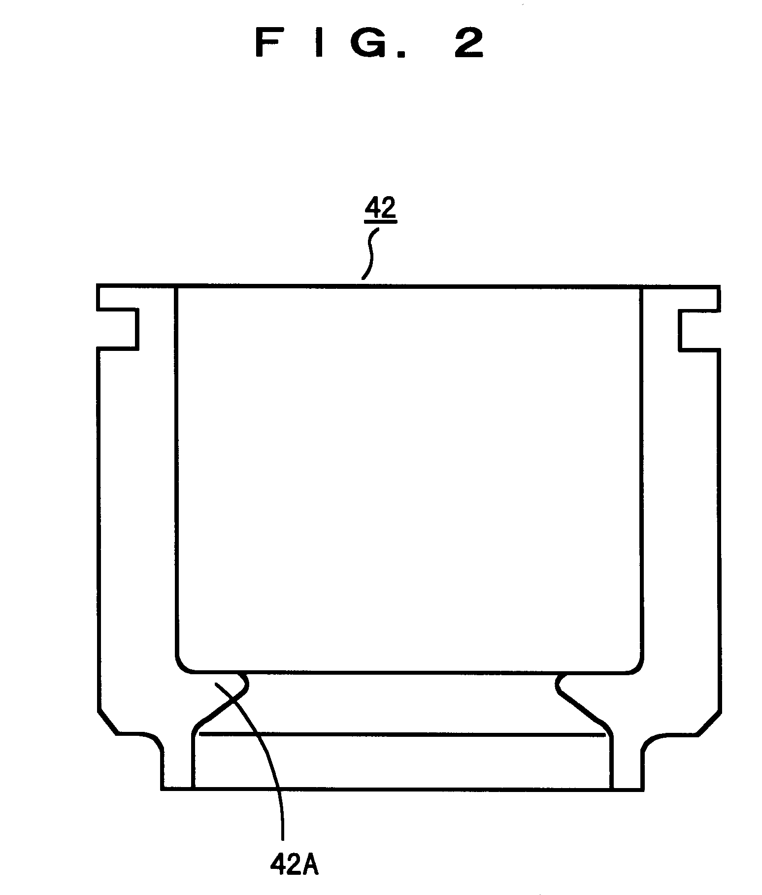
A presently preferred embodiment of a clamping device according to the present invention will now be explained with reference to FIGS. 1, 2, 3A, 3B, 3C, 3D, 4A, 4B, 4C, and 4D.

In the illustrated embodiment, a cylindrical spindle 1 having a tapered socket 11 which holds the tapered shank tool holder 2 formed on one end thereof, and has an axial hole 12 which connects to the tapered socket 11 is provided. The spindle 1 is supported for rotation by upper and lower angular bearings 30 and 31 having ceramic balls. The tapered shank tool holder 2 has a tapered shank 21 which is complementary to the tapered socket 11, and a knob 22 which protrudes from the tapered end thereof. Furthermore, the spindle 1 has two keys 13 which fit into a key channel on the tapered shank tool holder 2. The keys are formed on the perimeter edge of the opening in tapered socket 11. A group of long holes 14, formed on the other end of the spindle 1, are aligned with the axis thereof. The respective long holes 14...


PUM

PropertyMeasurementUnit
spring forceaaaaaaaaaa
bias forceaaaaaaaaaa
spring forceaaaaaaaaaa

Abstract

A machine tool tool changing device including a circular array of multiple collet fingers (5) housed in the shaft hole (12) of a spindle (1) capable of turning between a clamped position in which a tool holder (2) knob (22) is clamped and an unclamped position in which the knob is released, a collet sleeve (6) which surrounds the circular array of collet fingers and arrests the turning of same, an air cylinder which moves the collet sleeve axially relative to the collet fingers and releases the arresting of the collet fingers, a first plate spring (43) which exerts a strong force on the knob toward the spindle through the collet fingers, an air cylinder which removes the force exerted by the first plate spring, and a second plate spring (46) which exerts a force to maintain the collet fingers in the clamped position in opposition to the weight of the tool holder even if the collet fingers rotate and the force exerted by the first plate spring is removed.

Description

The present invention relates to a machine tool. More particularly, the invention relates to a clamping device for holding a tool holder such that the tool can be released to a hollow rotating spindle.BACKGROUND TECHNOLOGYIn general, tapered shank tool holders having a knob on the tapered end are releasably held within a tapered socket on a complementary, hollow rotating spindle. The spindle has an axial hole which penetrates through the tapered socket, collet fingers which grip the tapered shank tool holder knob, and a draw bar connected to the collet fingers, housed so as to be able to slide in the shaft hole. The collet fingers are turnable in the space between the knob-gripping clamped position and the knob-releasing unclamped position. The draw bar is movable in the axial direction of the spindle between an operating position in which the tool holder is held in the spindle tapered socket and a non-operating position, in which the tool holder is released from the tapered socket....

Claims


Application Information

Patent Timeline
Patent Type & Authority Patents(United States)
IPC IPC(8): B23B31/02B23B31/26B23Q3/12
CPCB23B31/261Y10T279/3481Y10T409/309464Y10S279/90
Inventor HASHIDATE, AKITAKEMISAWA, KEITA
Owner SODICK CO LTD
Why Eureka
Try Eureka