
Lateral suspension assembly for a guided vehicle system

a technology of lateral suspension and vehicle system, which is applied in the direction of suspensions, rope railways, transportation and packaging, etc., can solve the problems of lateral bounce and uncomfortable "head toss", noise, head toss and other passenger discomfort, wear and damage to the vehicle, annoying and dangerous roll forces on the passenger and vehicle, etc., to reduce the necessary guideway width and tolerances for power collection, reduce head toss and roll, and improve guidance and lateral stability

Inactive Publication Date: 2001-10-09
RAYTHEON CO
View PDF65 Cites 9 Cited by
  • Summary
  • Abstract
  • Description
  • Claims
  • Application Information

AI Technical Summary

Benefits of technology

It is a further object of this invention to provide such a lateral suspension assembly which reduces head-toss and roll and provides improved guidance and lateral stability.
It is a further object of this invention to provide such a lateral suspension assembly which avoids hunting and bounce and maintains a constant contact between the lateral wheels and guide rails despite wind loads and guide rail deviations.
It is a further object of this invention to provide such a lateral suspension assembly which reduces necessary guideway width and tolerances for power collection and communication antennas.

Problems solved by technology

In one approach this is done with lateral rollers that engage the lateral rails and continuously hunt from side to side resulting in lateral bounce and uncomfortable "head toss".
As a result the vehicle swings from side to side causing noise, head toss and other passenger discomfort and wear and damage to the vehicle.
In addition, the force of friction between the tires and their footprint on the guideway is a significant distance from the center of gravity of the vehicle, causing annoying and dangerous roll forces on the passenger and vehicle.
In such approaches the wide range and unpredictability of movement of the guide wheels and the vehicle as a whole require wider guideways and greater tolerances for power collection and communications and makes the lateral wheels' motion unreliable as an indicator of vehicle distance and position.

Method used


Image

  • Lateral suspension assembly for a guided vehicle system
  • Lateral suspension assembly for a guided vehicle system
  • Lateral suspension assembly for a guided vehicle system

Examples


Embodiment Construction

Other objects, features and advantages will occur to those skilled in the art from the following description of a preferred embodiment and the accompanying drawings, in which:

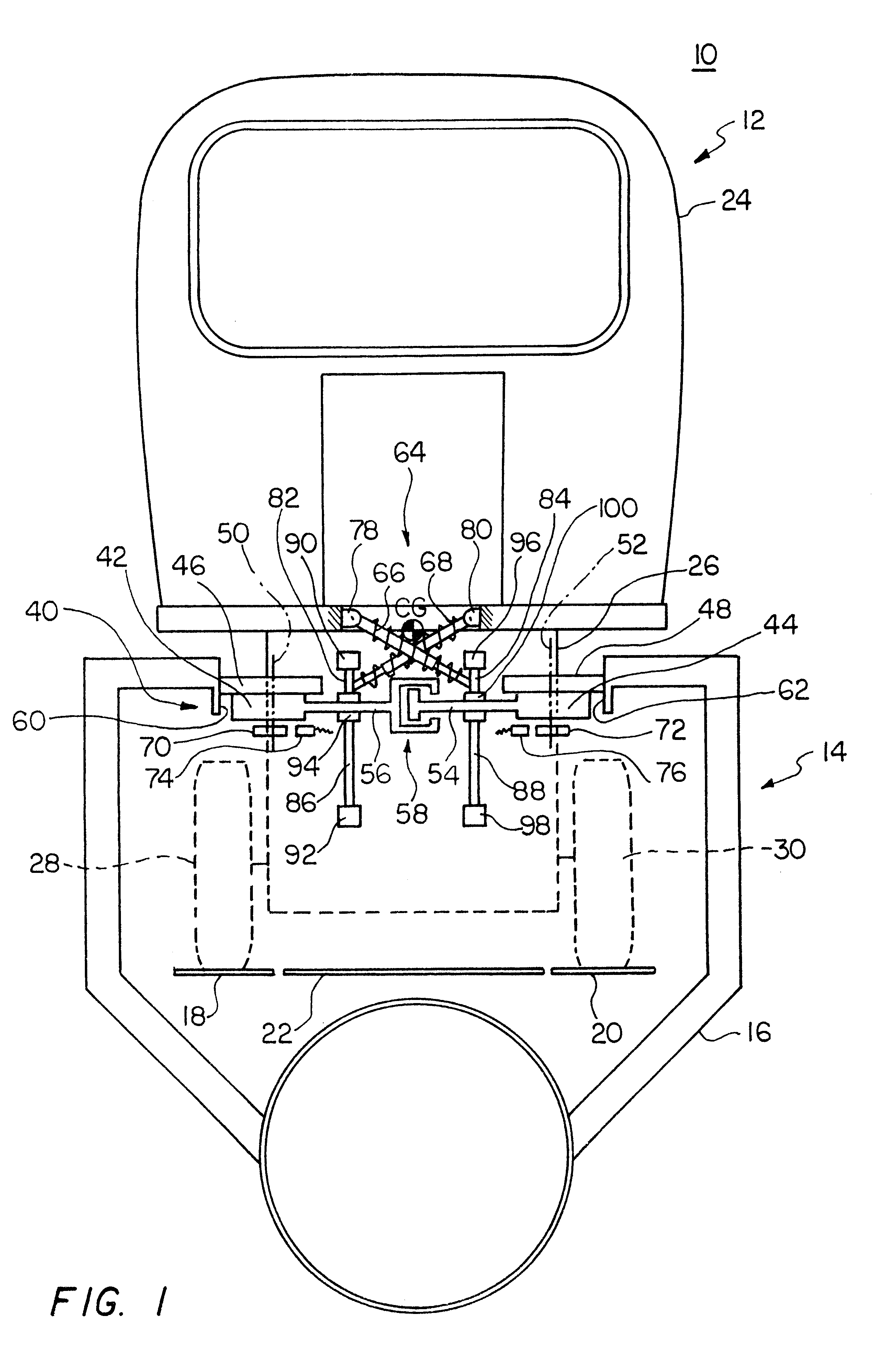
FIG. 1 is a schematic end view of a guided vehicle and guideway of a guided vehicle system using a lateral suspension assembly according to this invention;

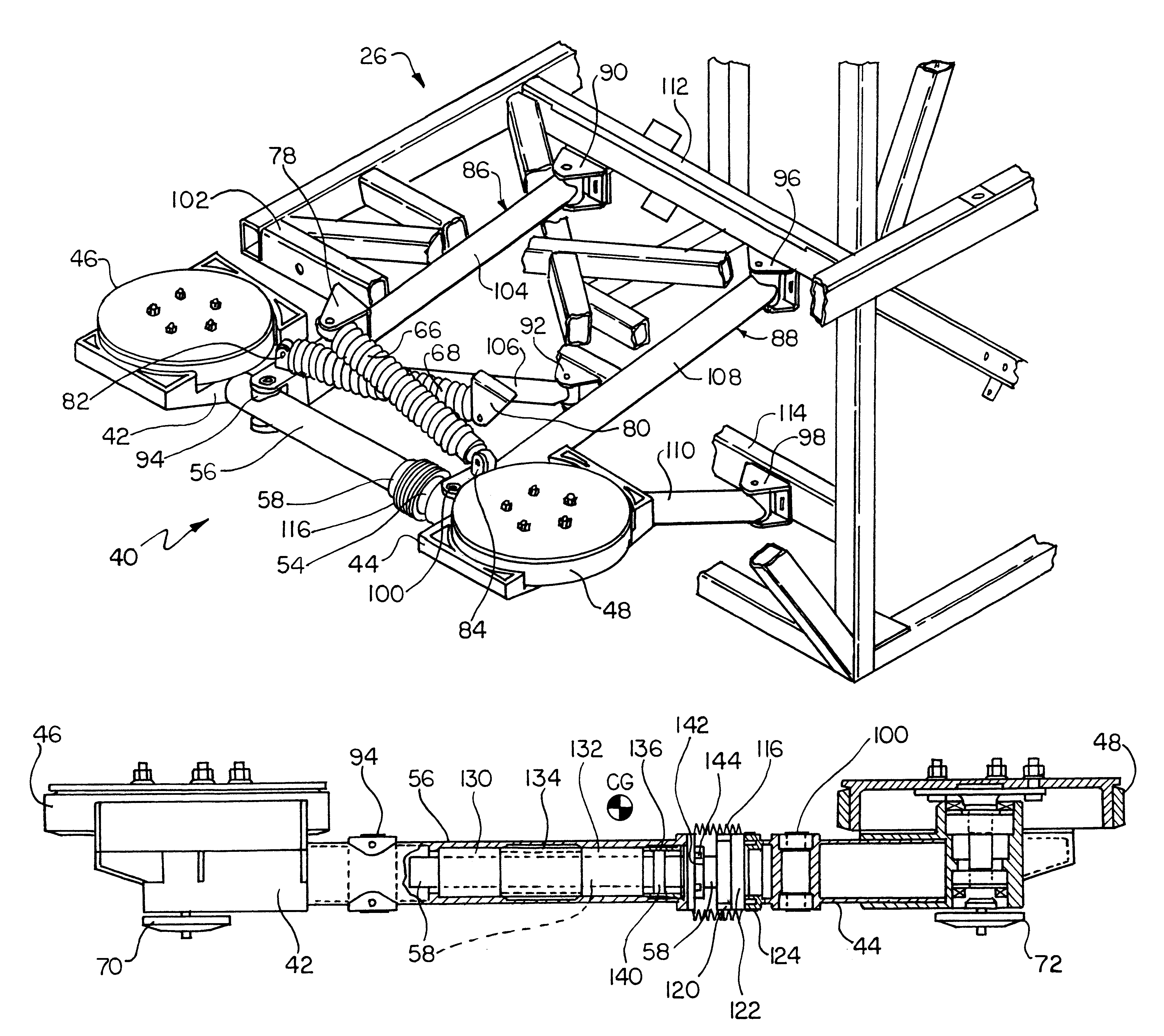
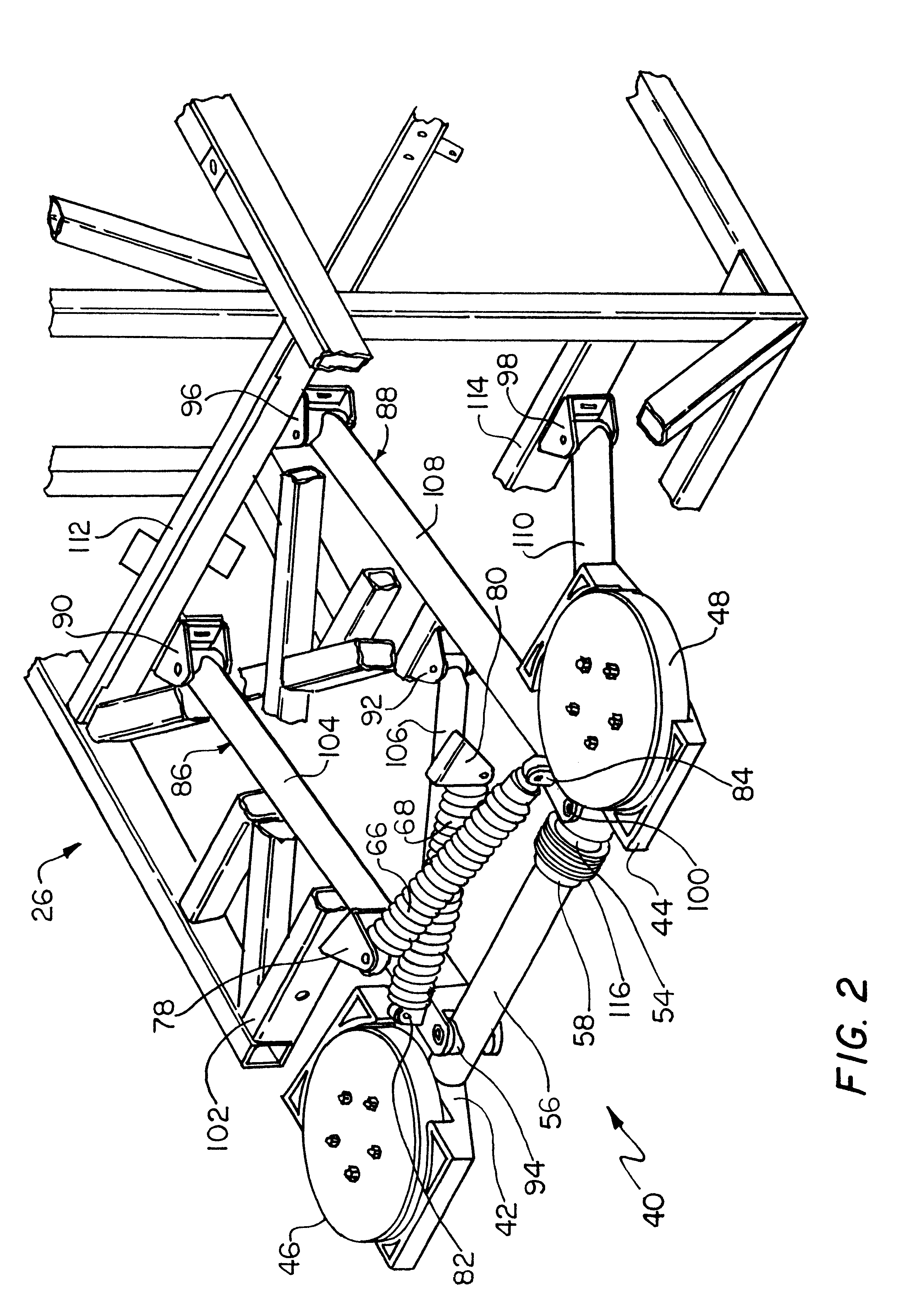
FIG. 2 is a three-dimensional diagrammatic view of the lateral suspension assembly of FIG. 1 and the vehicle chassis frame;

FIG. 3 is a schematic side view of one end of the guided vehicle showing the support arms and other portions of the lateral suspension assembly of FIG. 2; and

FIG. 4 is a front elevational sectional view of the lateral wheel housings, lateral wheels and lateral limit link of FIG. 2.

There is shown in FIG. 1 a guided vehicle system 10 including a vehicle 12 which moves on guideway 14. Guideway 14 includes a support structure 16 including main running surfaces 18 and 20 and a walkway or grate 22. Guided vehicle 12 includes cabin 24 mounted on...


PUM


Abstract

A lateral suspension assembly for a guided vehicle system includes a pair of lateral wheel housings each including a lateral wheel rotatable about spaced vertical axes for engaging spaced opposing guide rails of the guided system; a lateral limit link for limiting outward travel of the lateral wheels beyond a predetermined limit; a pair of spaced support arms pivotably attached at one end to the guided vehicle and at the other to the lateral wheel housings; and a biasing device interconnected with each of the wheel housings for urging the lateral wheels in contact with the guide rails.

Description

This invention relates to a lateral suspension assembly for a guided vehicle system.BACKGROUND OF INVENTIONConventional laterally guided vehicles rely on lateral guide rails to stabilize and direct them along the guideway. In one approach this is done with lateral rollers that engage the lateral rails and continuously hunt from side to side resulting in lateral bounce and uncomfortable "head toss". This occurs because the lateral rollers on each side are fixed together in a four bar linkage so that any bump in a guide rail will be translated from the associated lateral guide roller to the entire mechanism and steer the castered support tires to move the vehicle in the other direction from the bump. Thus the vehicle is urged toward the other guide rail. As a result the vehicle swings from side to side causing noise, head toss and other passenger discomfort and wear and damage to the vehicle. In another approach, in order to avoid the head-toss problem the support tires are constantly...

Claims


Application Information

Patent Timeline
IPC IPC(8): B61B13/04B62D1/26B62D1/00
CPCB61B13/04B62D1/265B60G2200/34B60G2200/345B60G2202/312B60G2204/423B60G2300/10B60G2300/102B60G2400/204
Inventor COLLINS, DAVID C.LEWIS, ALBERT E.GARNEAU, JR., GERALD A.
Owner RAYTHEON CO
Learn More