Trencher plow for laying pipe

Inactive Publication Date: 2001-10-09
LIEBRECHT JR SYLVESTER J
View PDF1 Cites 26 Cited by
  • Summary
  • Abstract
  • Description
  • Claims
  • Application Information

AI Technical Summary

Problems solved by technology

Although separate commercially available self powered auger and trencher machines can be designed to operate at somewhat faster speeds, the need in most instances is not for such faster speed.

Method used


Image

  • Trencher plow for laying pipe
  • Trencher plow for laying pipe
  • Trencher plow for laying pipe

Examples


Embodiment Construction

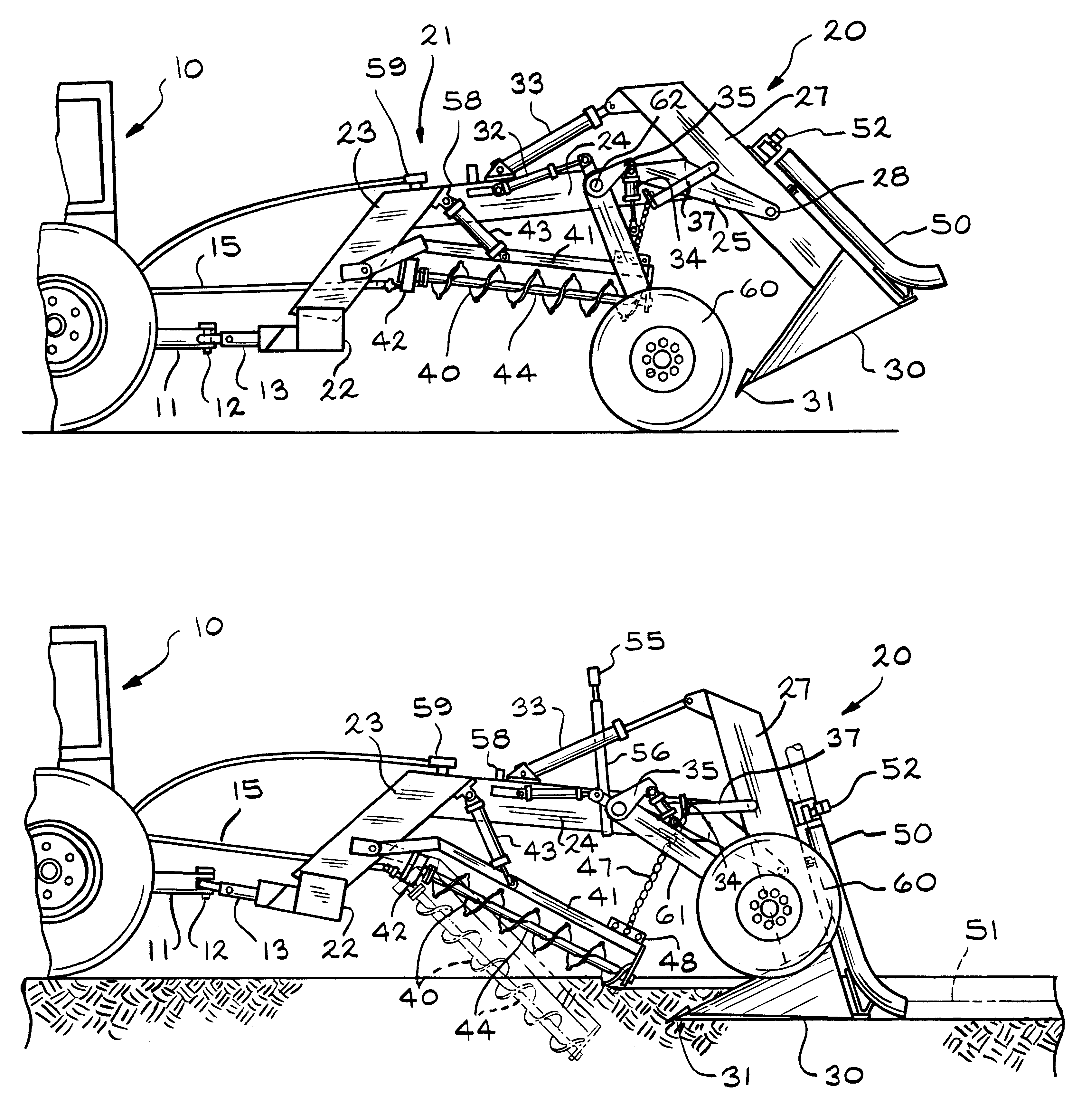
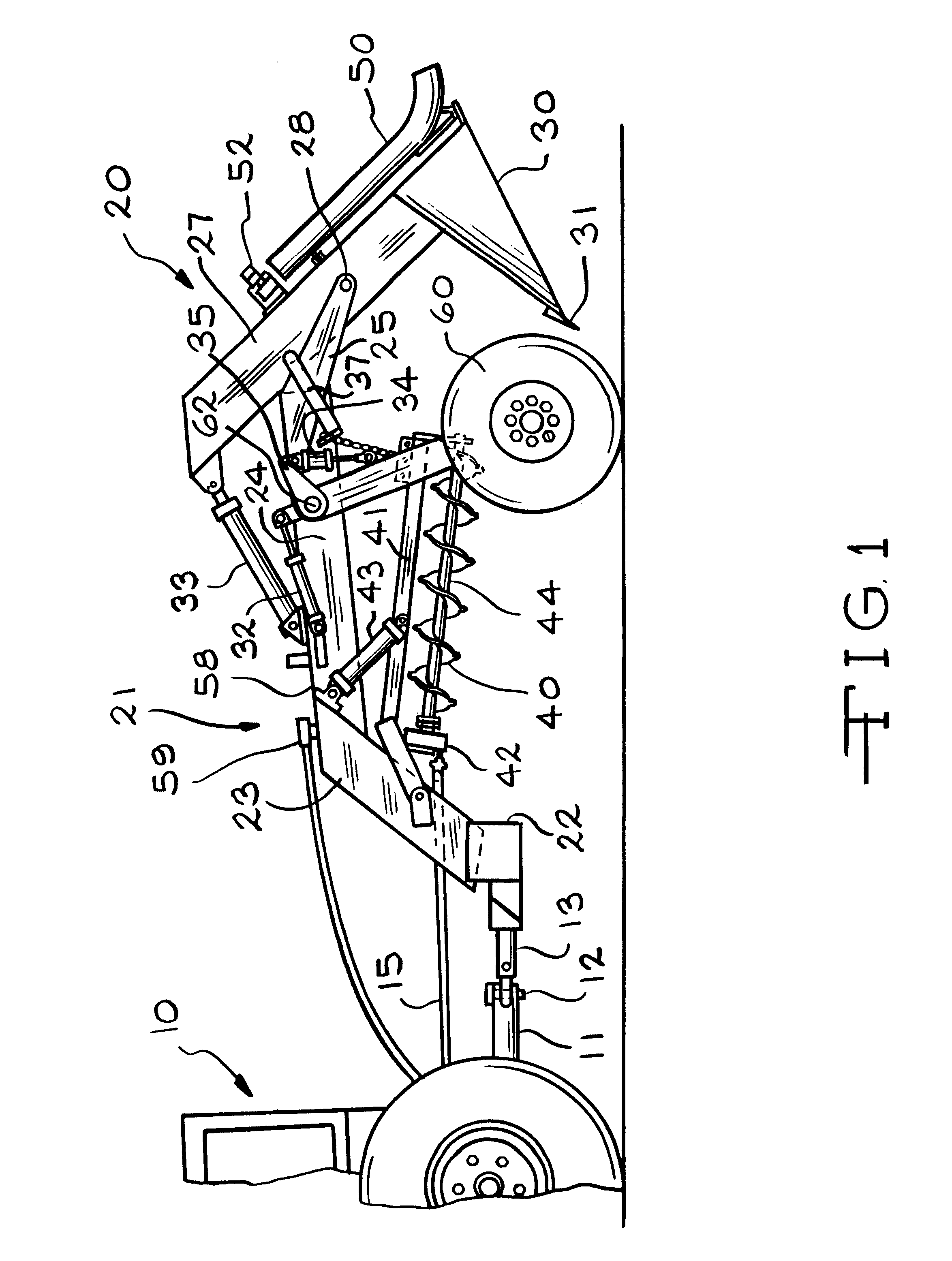
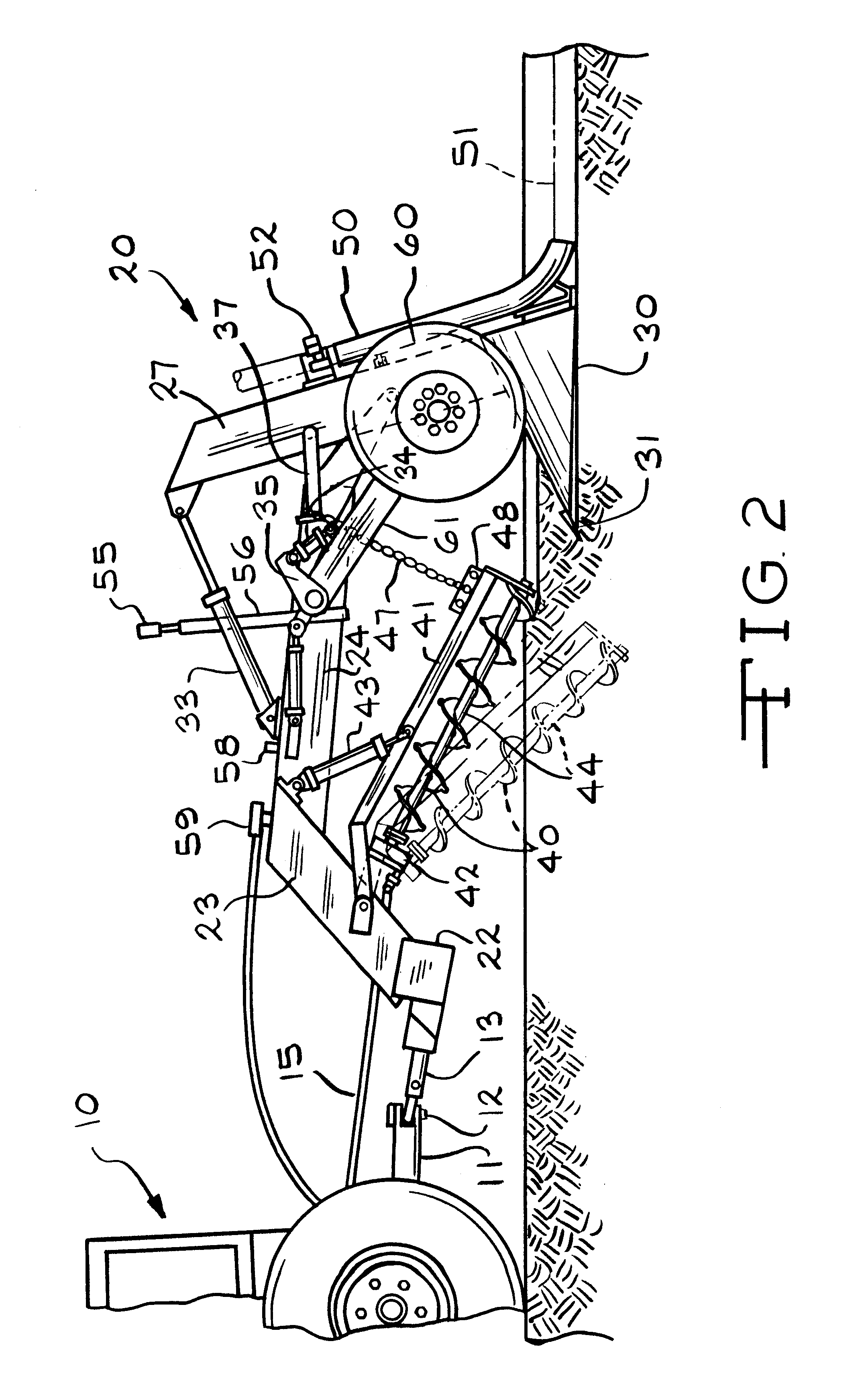
Turning to the drawings in greater detail, FIG. 1 illustrates an exemplary form of the machine of the invention connected to be drawn by a tractor 10, with only the rear portion shown, having a towbar 11 connected by a coupling 12 to a pull shaft 13 for the trencher plow machine 20 of the invention. The machine 20 incorporates as its principal components a plow 30 with an auger 40 located in advance of the plow. FIG. 1 illustrates the machine with the auger 40 and the plow 30 both lifted above ground level for transport of the machine from place to place.

The auger and plow are mounted on a frame support or superstructure 21 connected to a drawbar 22. The superstructure 21 includes a pair of upwardly extending parallel support arms 23 with a rearward extending support arm 24 connected therebetween. A pair of side by side plow support members 25 extend from the support arm 24 between which and on which a plow shank or arm 27 is mounted in pivoted relation. The plow arm 27 extends both...


PUM


Abstract

A trencher plow for laying pipe such as drainage pipe which includes in combination an auger angled downwardly toward a plow which follows, both mounted in a superstructure and being arranged to be cooperatively raised and to set the grade and depth of cut by the plow determinable by sensing the grade setting signal of a laser unit located in the field of cut. The auger is provided with cutting lobes distributed about its teeth which facilitate cutting and throwing soil to the sides of a trench being dug in advance of the plow which finalizes shaping of the trench for deposition of pipe into the trench.

Description

FIELD AND BACKGROUND OF THE INVENTIONThe present invention is a new trencher plow for laying flexible pipe such as drainage pipes having perforations for subsurface drainage. The invention includes, in combination, a plow and a horizontal auger mounted in a frame or superstructure in which the plow is supported over the auger. In operation the auger is angled downwardly toward a cutting boot on the plow such angle being about 60 degrees dependant upon the depth of the trench being dug by the plow drawn immediately behind.The auger of the invention having the usual helically distributed and angled teeth is uniquely provided with spaced projections such as lobes mounted on its teeth which during the auger rotation are effective in digging into soil. At operating speeds of the invention, the auger with its lobes is effective in throwing the soil to both sides of a trench being formed. The boot of the plow following immediately behind the auger is selected to have a width adequate to fo...

Claims


Application Information

Patent Timeline
Patent Type & Authority Patents(United States)
IPC IPC(8): E02F3/04E02F3/06E02F5/10E02F5/12E02F5/02
CPCE02F3/06E02F5/04E02F5/102E02F5/12
Inventor LIEBRECHT, JR., SYLVESTER J.
Owner LIEBRECHT JR SYLVESTER J
Why Eureka
Try Eureka