Telescoping handle assembly for luggage and other luggable items

a technology for telescoping handles and luggage, which is applied in the direction of wing knobs, furniture parts, manufacturing tools, etc., can solve the problems of limiting the leverage that is available to a traveler, causing travelers to suffer unnecessary wrist and forearm fatigue,

Inactive Publication Date: 2001-10-16
PARAGAON LUGGAGE
View PDF14 Cites 67 Cited by
  • Summary
  • Abstract
  • Description
  • Claims
  • Application Information

AI Technical Summary

Problems solved by technology

For this reason, prior art telescoping handle assemblies often subject travelers to unnecessary wrist and forearm fatigue and, in some instances, pain.
Prior art telescoping handle asse

Method used


Image

  • Telescoping handle assembly for luggage and other luggable items
  • Telescoping handle assembly for luggage and other luggable items
  • Telescoping handle assembly for luggage and other luggable items

Examples


Embodiment Construction

In an effort to highlight various embodiments and innovative aspects of the present invention, a number of sub-headings are provided in the following discussion. In addition, where a given structure appears in several drawings, that structure is labeled using the same reference numeral in each drawing.

Prior Art Handle Assemblies

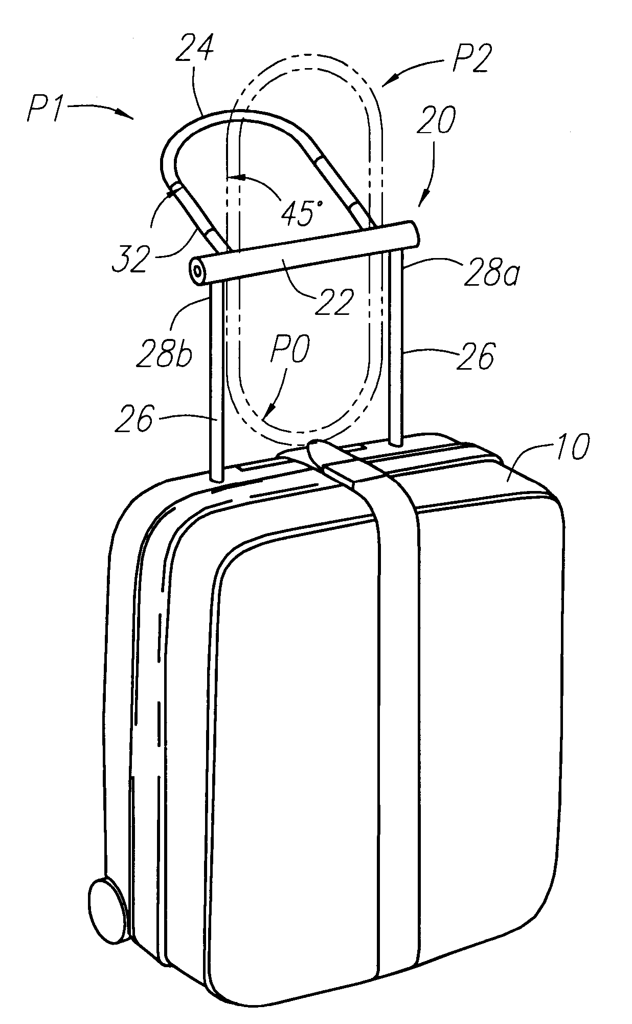
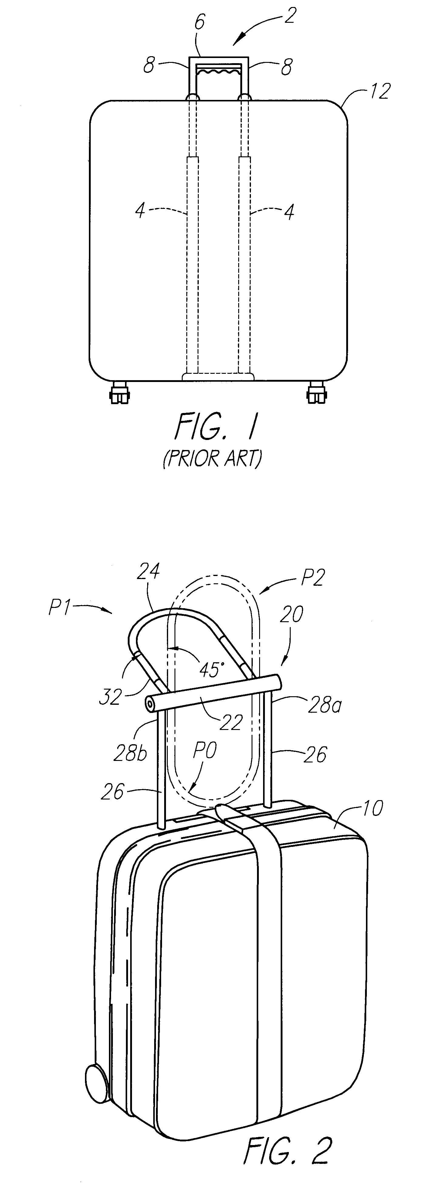
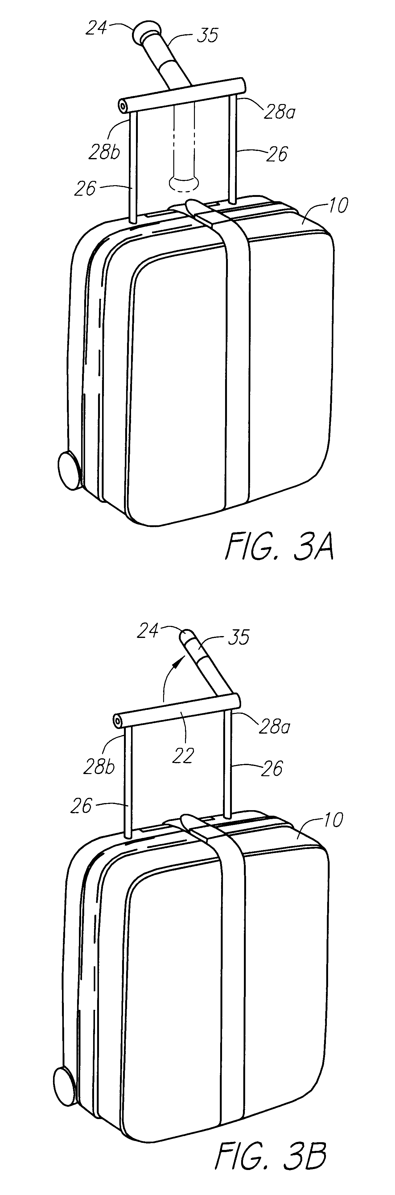
Turning now to the drawings, as shown in FIG. 1, typical prior art telescoping handle assemblies 2 for use on luggage and other luggable items generally include a pair of telescoping support members 4 having a handle 6 mounted between their distal extremities 8. It will be appreciated that the handle 6 of such handle assemblies 2 has a central axis 10 that is fixed in an orthogonal relationship to the direction that a bag 12 attached to the handle assembly is designed to be pulled (or pushed) in. For this reason, prior art telescoping handle assemblies often subject travelers to unnecessary wrist and forearm fatigue and, in some instances, pain. Prior art tel...


PUM


Abstract

A telescoping handle assembly for luggage or other luggable items. A telescoping handle assembly is provided that includes a primary handle and a secondary handle. The secondary handle provides at least one gripping surface that, when deployed, may extend in a direction generally parallel to a direction that a traveler may move when transporting an item attached to the secondary handle from one location to another.

Description

The present invention relates generally to luggage and, more particularly, to improved telescoping handle assemblies for use on luggage and other luggable items including, for example, suit cases, brief cases, instrument cases, document bags, garment bags and the like.Over the last few years, substantial attention has been directed toward the development of wheeled luggage items. Such items generally comprise a container (or case) for enclosing one or more items of clothes, toiletries and the like, a wheel assembly and an extendable or telescoping handle assembly. The wheel assembly and extendable handle assembly are affixed to the container such that the container may be pulled fairly easily from one point to another, for example, through an airport. In addition, conventional handle assemblies generally include a pair of telescoping support members that have a cross-bar or handle provided between their distal extremities. When configured in an extended position, the cross-bar or ha...

Claims


Application Information

Patent Timeline
IPC IPC(8): A45C13/26A45C13/00A45C13/22
CPCA45C13/22A45C13/262Y10T16/455Y10T16/451
Inventor MYERS, JAY EVANDUDLEY, FRANCISSTOCKS, DAVID LAURENCE
Owner PARAGAON LUGGAGE
Why Eureka
Try Eureka