Lift dolly with pedal latch mechanism

Inactive Publication Date: 2001-11-06
HOME DEPOT PROD AUTHORITY
View PDF7 Cites 37 Cited by
  • Summary
  • Abstract
  • Description
  • Claims
  • Application Information

AI Technical Summary

Problems solved by technology

However, cranes are generally expensive and complex.
However, these simple dollies are not capable of moving heavy equipment.
While the invention described in U.S. Pat. No. 5,876,173 is capable of lifting and transporting machine tools, it has been discovered that the latching mechanism is difficult for a user to

Method used


Image

  • Lift dolly with pedal latch mechanism
  • Lift dolly with pedal latch mechanism
  • Lift dolly with pedal latch mechanism

Examples


Embodiment Construction

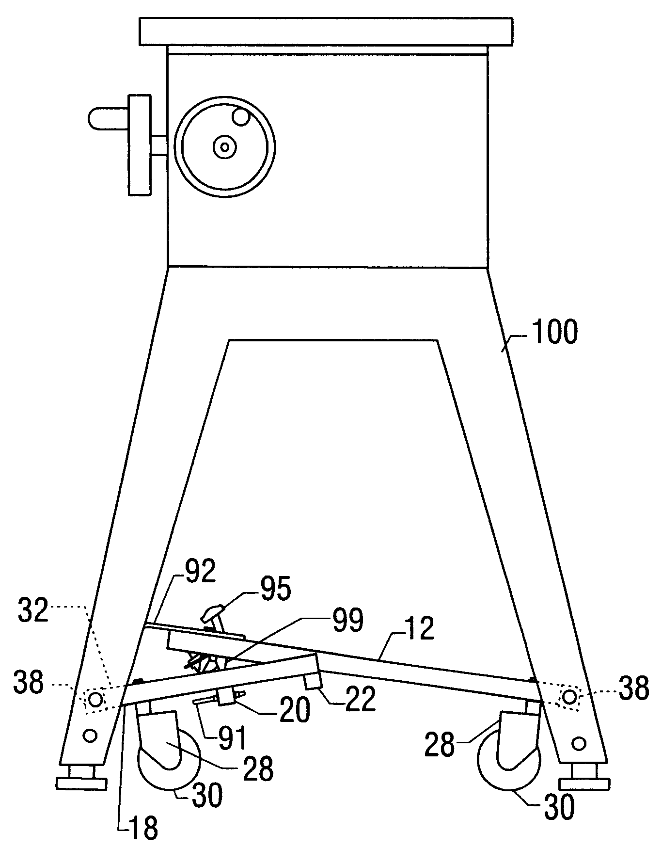
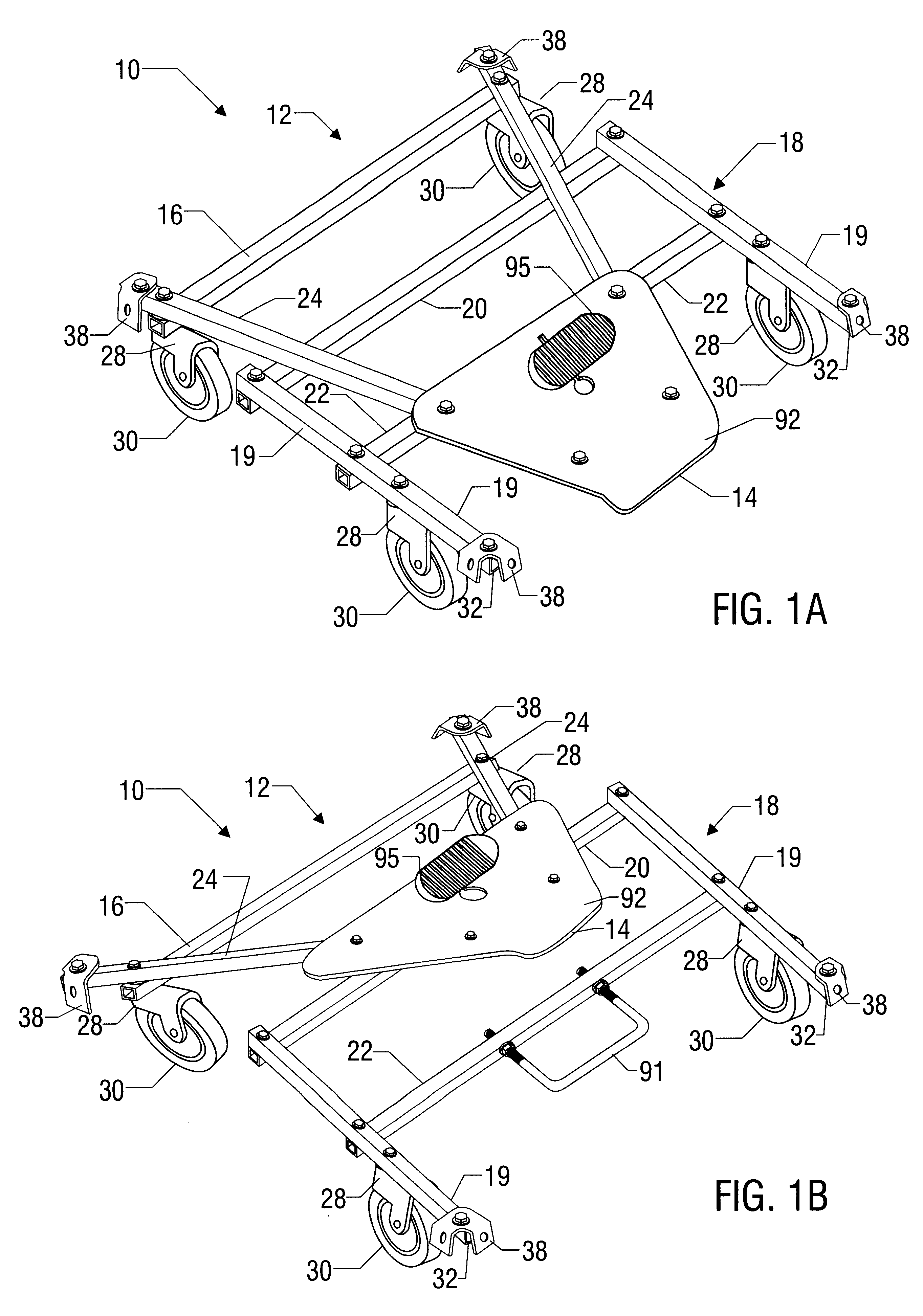
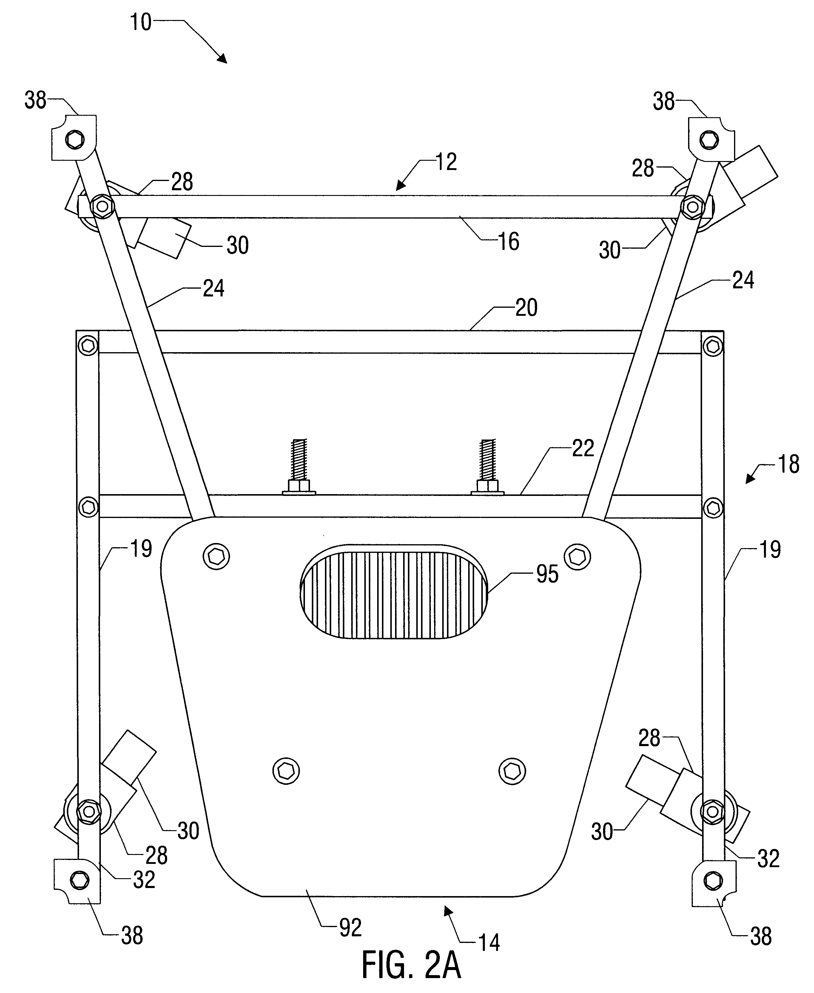
The invention relates to an apparatus for lifting and transporting an object. In some embodiments, the lift dolly employs a pedal latch mechanism that attaches to a U-bolt to securely lock the lift dolly in the position of lifting a heavy object. Use of this pedal latch provides a secure attachment of the frames of the lift dolly, thus ensuring that the heavy object will not be dropped. Further, once the object has been moved to a desired new location, a user may depress the pedal on the latching mechanism to easily lower the object. Because the pedal latch may be disengaged by the user's foot pushing on the pedal, the user may easily and quickly disengage the lifting mechanism.

In some embodiments of the invention, a bracket is included which helps to guide a locking member, or a U-bolt, into locking position. The bracket can be V-shaped, and could also be integrally formed in the footplate by lancing tabs directly into the footplate, for example. Further, the locking member or U-bo...


PUM


Abstract

A lift dolly apparatus is described for use in lifting and transporting objects. A latching mechanism is described which securely latches the dolly in the lifted position and can be easily released by using a foot pedal.

Description

1. Field of the InventionThe invention relates to a lifting device for moving heavy objects. More particularly, this invention relates to a lift dolly possessing a latch mechanism for securely locking the dolly in a lifted position.2. Description of the Related ArtOften it is desirable to move heavy equipment in a timely fashion. Many devices are available for moving equipment on the factory floor or in a workshop. Some devices such as cranes are capable of transporting and lifting extremely heavy equipment. However, cranes are generally expensive and complex.Alternatively, simple dollies that pivot about an axle are extremely portable and easy to use. However, these simple dollies are not capable of moving heavy equipment.Therefore, it is desirable to provide a machine that is capable of lifting and moving heavy equipment in a simple method and timely fashion.One attempt at providing such a lift dolly is disclosed in U.S. Pat. No. 5,876,173 to English, incorporated by reference in ...

Claims


Application Information

Patent Timeline
IPC IPC(8): B62B5/00
CPCB62B5/0083B62B2203/10B62B2205/23
Inventor THEISING, JOHN L.
Owner HOME DEPOT PROD AUTHORITY
Why Eureka
Try Eureka