Fastener pulling tool

a technology of fastener and tool, which is applied in the direction of nail extractor, multi-purpose tool, pliers, etc., can solve the problems of staple bending, post breaking, and difficulty in removing staples

Inactive Publication Date: 2001-11-13
HAY PATRICK JAMES
View PDF15 Cites 27 Cited by
  • Summary
  • Abstract
  • Description
  • Claims
  • Application Information

AI Technical Summary

Problems solved by technology

Without a proper tool, it is difficult to remove the staple once it has been driven tightly against a strand of wire making up the fence.
This usually results in the bending of the staple, and when the post is of small diameter, it may become necessary to attempt to finish the pull by exerting a pull straight outward and without the advantage of leverage.
Also, one frequent reason for removing the staples to release the fencing wires from the post is that the post has been broken, usually at or slightly above ground level.
In this situation, it becomes virtually impossible to exert any withdraw force on the staple by turning the plier in a horizontal plane because this simply causes the post to effectively twist about its own longitudinal axis.
However, the principle of attempting to remove a staple by pulling on the wire being held by the staple is not usually practical.
When a staple has been driven tightly into the post, the horizontal strand of wire being held thereby is usually buried in the post under the bight of the staple, thus making it extremely difficult to force the pincer points behind the wire to achieve any pull on the w...

Method used


Image

  • Fastener pulling tool
  • Fastener pulling tool
  • Fastener pulling tool

Examples


Embodiment Construction

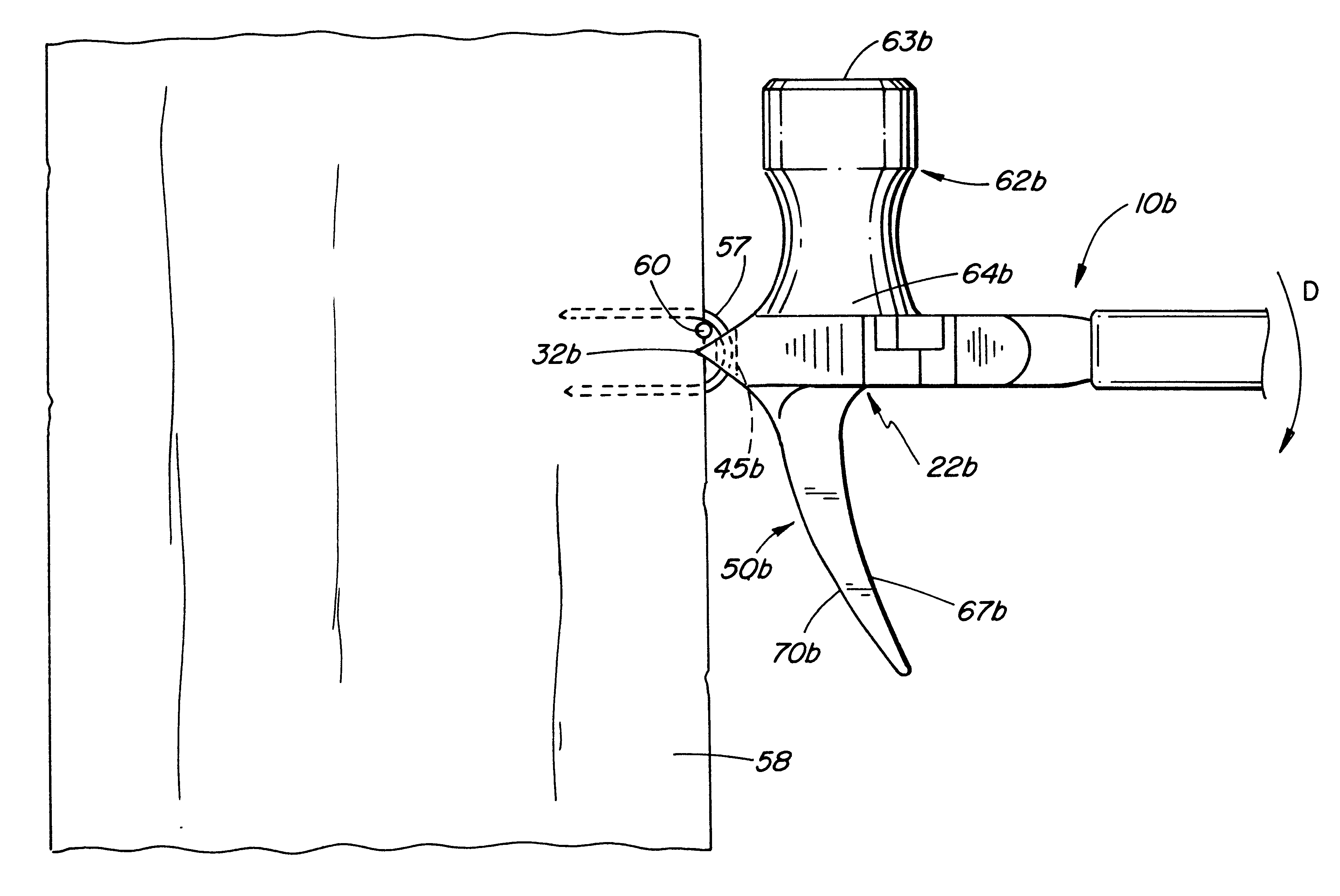
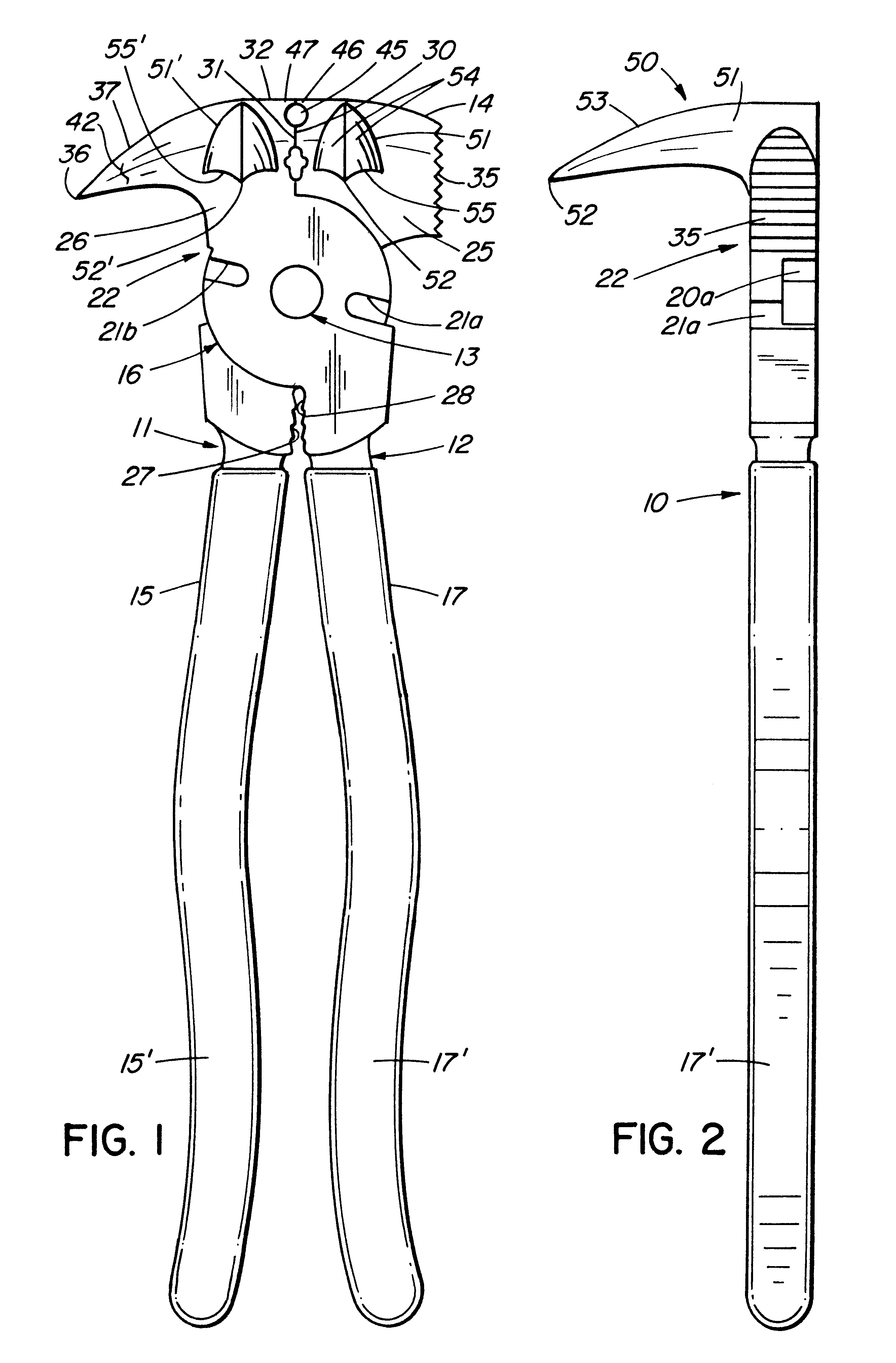
In the drawings, reference numbers denoting parts of the structure correspond to the reference numbers used herein to describe like parts, and reference number 10 generally denotes one embodiment of the present invention in the form of a fencing plier. As is common to the design of fencing pliers, the tool 10, hereinafter referred to as a plier, consists of two elongated members 11 and 12 connected together in a scissor fashion by way of a pivot means 13 which is closer to the upper end of the fencing plier. It should be appreciated that while the plier is generally used in any orientation, for the sake of convenience, reference is made to the jaw or head end of the plier, as is shown in FIG. 1, as being the upper end of the fencing plier 10.

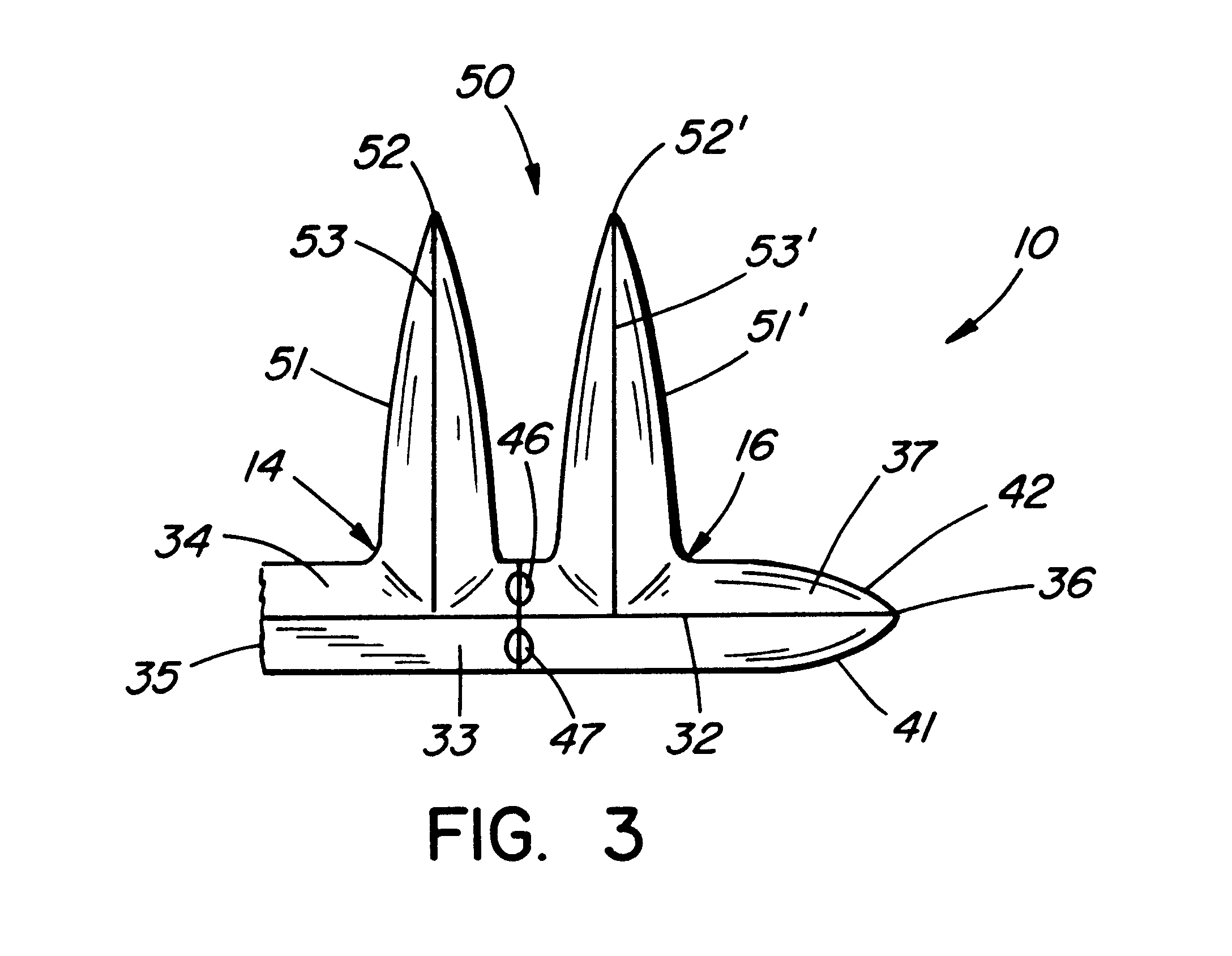
The elongated member 11 is normally formed as an integral unit, such as by casting, and includes a jaw portion 14 and a handle portion 15, and similarly the elongated member 12 includes a jaw portion 16 and a handle portion 17 formed integrally ...


PUM


Abstract

A staple pulling plier of the type consisting of a pair of pivoting members having handles and jaws forming a head portion. The head portion has opposite side faces, and the jaws in a closed position define a substantially continuous post engaging top ridge. Pincer points are provided on the jaws adjacent the top ridge and are moved to a closed staple grasping position on closure of the handles. A fulcrum member is formed integrally with the head portion and projects from one of the opposite side faces of the head portion, the fulcrum member defining an upper edge extending in a plane substantially normal to the post engaging top ridge of the jaws. When the bight of a staple is held by the pincer points, the two legs of the staple and the joining bight are in a plane normal to the post engaging top edge of the head portion. When the staple has been driven into a post to secure a horizontal strand of the fence, its plane is usually vertically disposed. Thus, as the plier is swung in a direction coinciding with the plane of the staple, the upper edge of the fulcrum member engages the post, and pressure can be applied in an up or down direction to more effectively withdraw the staple.

Description

This invention relates to a fastener pulling tool such as a plier used in fencing operations including fence repairs when it is necessary to loosen or remove staples, nails and the like from posts.BACKGROUND TECHNOLOGYVarious tools are used in building, repairing or removing fencing. A common form of fencing which has been in use for many years consists of barbed wire and / or page wire fencing which is stretched tightly and fastened to wooden posts by way of metal staples driven into the post. Without a proper tool, it is difficult to remove the staple once it has been driven tightly against a strand of wire making up the fence. The most common tool presently sold is designed for various uses in fencing, and this tool, which is designed for removing staples, is a more modern version of the tool shown in U.S. Pat. No. 1,949,335, Feb. 27, 1934 to Settles. While variations of this tool are still being developed, see for example U.S. Pat. No. 5,303,748, Apr. 19, 1994 and U.S. Pat. No. 5,...

Claims


Application Information

Patent Timeline
IPC IPC(8): B25C11/00B25F1/00
CPCB25C11/00B25F1/006
Inventor HAY, PATRICK JAMES
Owner HAY PATRICK JAMES
Why Eureka
Try Eureka