Heat dissipation fan

a heat dissipation fan and fan body technology, applied in the direction of positive displacement liquid engine, piston pump, liquid fuel engine, etc., can solve the problems of difficult and tedious assembly of conventional heat dissipation fans, small heat dissipation fans, and small components of heat dissipation fans

Inactive Publication Date: 2001-11-20
HSIEH HSIN MAO
View PDF12 Cites 71 Cited by
  • Summary
  • Abstract
  • Description
  • Claims
  • Application Information

AI Technical Summary

Problems solved by technology

Consequently, the assembly of the conventional heat dissipation fan is very difficult and tedious.
In addition, because the heat dissipation fan usually works with a small object like the CPU of a computer, the volume of the heat dissipation fan must be small, and the components of the heat dissipation fan are very tiny.
This will further increase the difficulty and tedium of assembling the conventional heat dissipation fan.
Furthermore, the conventional heat dissipation fan does not have any oil guilds, so the lubrication oil easily flows out of the sleeve (38).
Consequently, the bearing will easily dry out, and the useful life of the heat dissipation fan will be decreased.

Method used


Image

  • Heat dissipation fan
  • Heat dissipation fan
  • Heat dissipation fan

Examples


Embodiment Construction

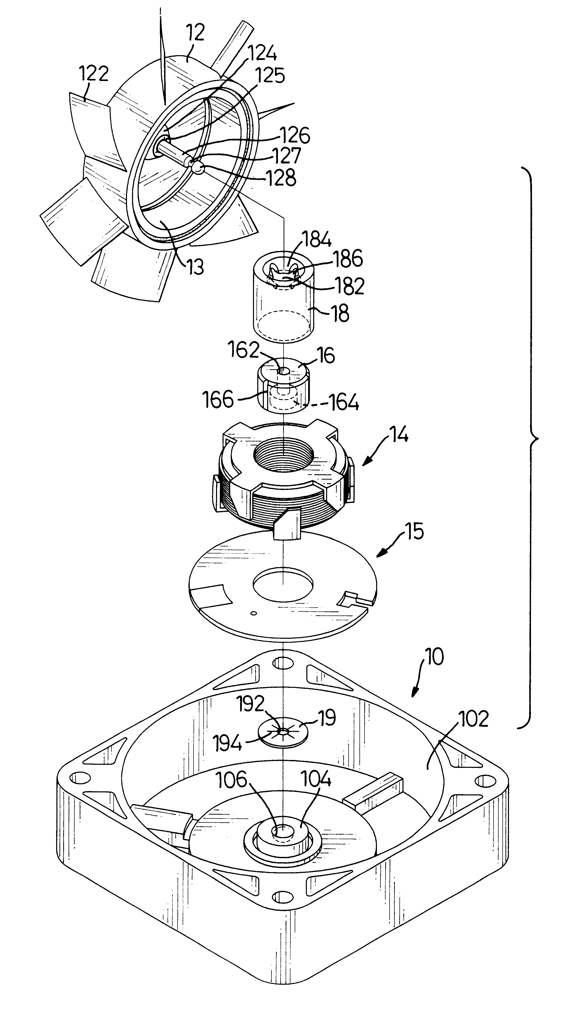
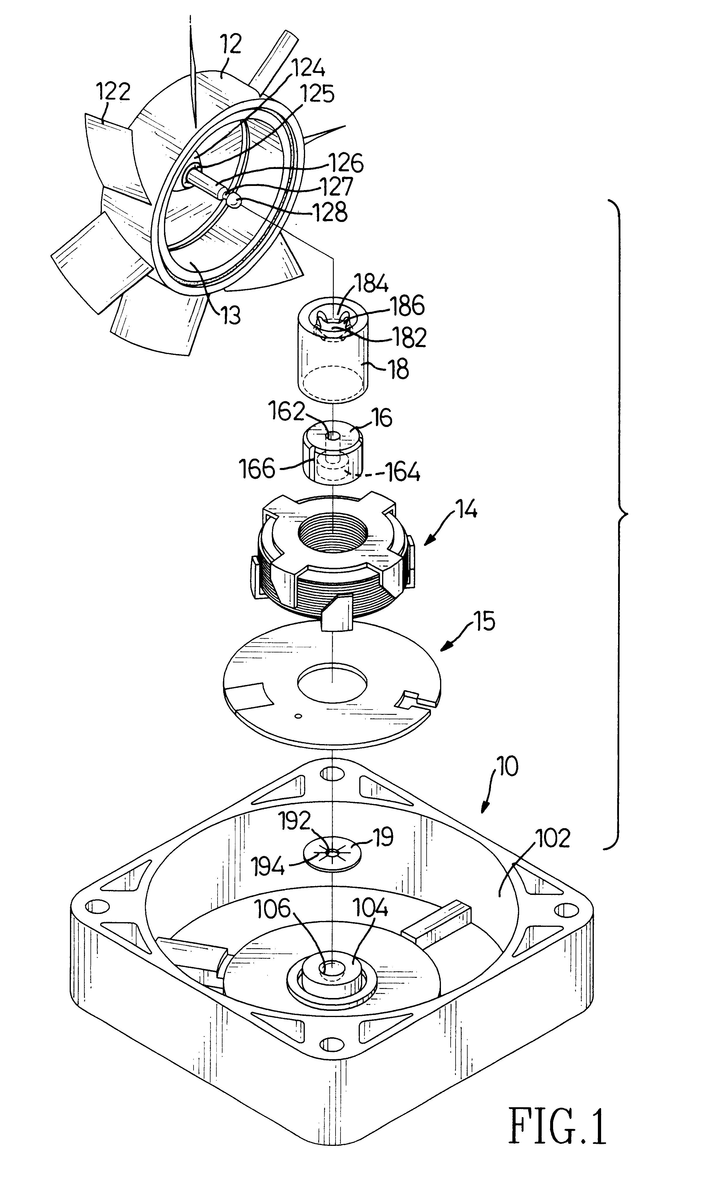
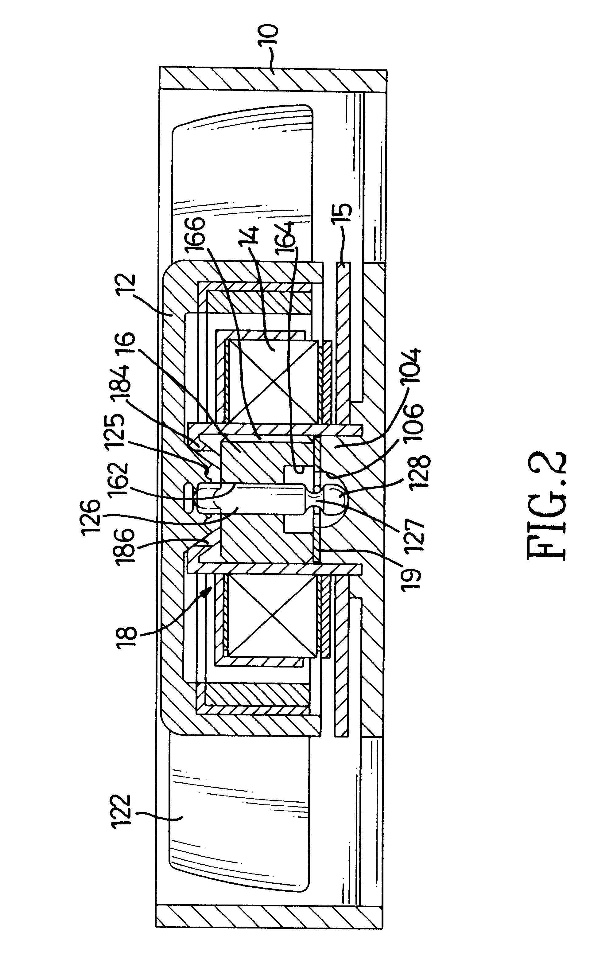
With reference to FIGS. 1 and 2, a heat dissipation fan in accordance with the present invention comprises a casing (10) and a fan (12) with multiple blades (122) arranged on the outer periphery rotatably mounted in the casing (10). A chamber (102) is defined in the casing (10) to receive the fan (12). A stator (14) is securely mounted in the chamber (102) of the casing (10). A permanent magnet (13) mounted in the fan (12) to be the rotor. A sleeve (18) is pressed into the stator (14) and is securely mounted in the casing (10) by pressing the central hole (182) of the sleeve (18) onto a protrusion (104) integrally formed at the center of the inside face of the casing (10) chamber (102).

A lubricating bearing (16) with lubrication oil contained therein is securely mounted in the sleeve (18). A central hole (162) is defined in the lubricating bearing (16). A chamber (164) communicating with the central hole (162) is defined in the bottom end of the lubricating bearing (16). At least on...


PUM


Abstract

A heat dissipation fan has a casing, a stator fixedly received in the casing, a sleeve with a central hole securely attached to the stator, a lubricating bearing with lubrication oil contained therein mounted in the sleeve, a fan rotatably mounted in the casing and having a magnet mounted therein to be a rotor, a shaft extending from the fan and securely received in the lubricating bearing and a locking disk securely mounted on the shaft to lock the lubricating bearing on said shaft. The lubricating bearing has a central hole defined therein, a chamber defined in the bottom end of said bearing and at least one oil groove longitudinally defined in the outer periphery of said bearing. This can lubricate the shaft and guide the lubrication oil to avoid noise and oil from leaking from the sleeve and drying out the bearing. Consequently, the useful life of the heat dissipation fan will be increased.

Description

1. Field of the InventionThe present invention relates to a heat dissipation fan, and more particularly to a heat dissipation fan that has a lubricating bearing with an oil guide to prolong the life of the heat dissipation fan.2. Description of Related ArtWith reference to FIG. 5, a conventional heat dissipation fan in accordance with the prior art comprises a casing (30) and a fan (32) rotatably mounted in the casing (30). A stator (34) with an electromagnet formed in the stator (34) is securely fixed in the casing (30). A permanent magnet (322) is mounted in the fan (32) to be a rotor, such that the fan (32) can rotate due to the interaction between the magnetic forces in stator (34) and the permanent magnet (322). A sleeve (38) is securely mounted on a base (302) formed in the casing (30) and pressed into the stator (34). A lubricating bearing (36) with lubrication oil contained therein is pressed into the sleeve (38). A shaft (324) extends from the fan (32) and through the beari...

Claims


Application Information

Patent Timeline
Patent Type & Authority Patents(United States)
IPC IPC(8): F04D25/06F04D25/02F04D29/04F04D29/057
CPCF04D29/057F04D25/062F04D25/0626
Inventor HSIEH, HSIN-MAO
Owner HSIEH HSIN MAO
Why Eureka
Try Eureka