Self-driving, self-locking and damping hinge strap, and a hinge fitted with such straps
a self-locking, hinge strap technology, applied in the direction of hinges, wing accessories, manufacturing tools, etc., can solve the problems of large shock at the end of deployment, large initial drawback of hinges of that type, and relatively complex implementation of hinges
- Summary
- Abstract
- Description
- Claims
- Application Information
AI Technical Summary
Benefits of technology
Problems solved by technology
Method used
Image
Examples
Embodiment Construction
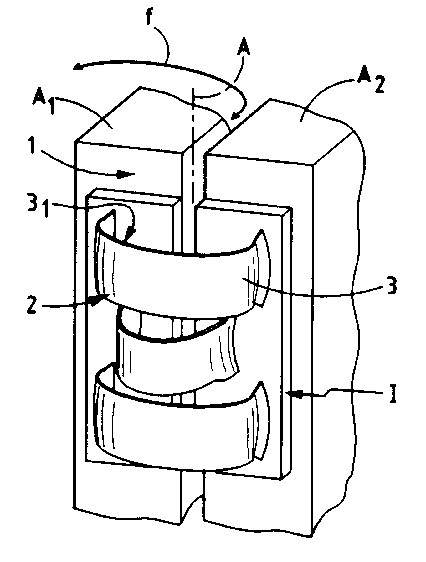
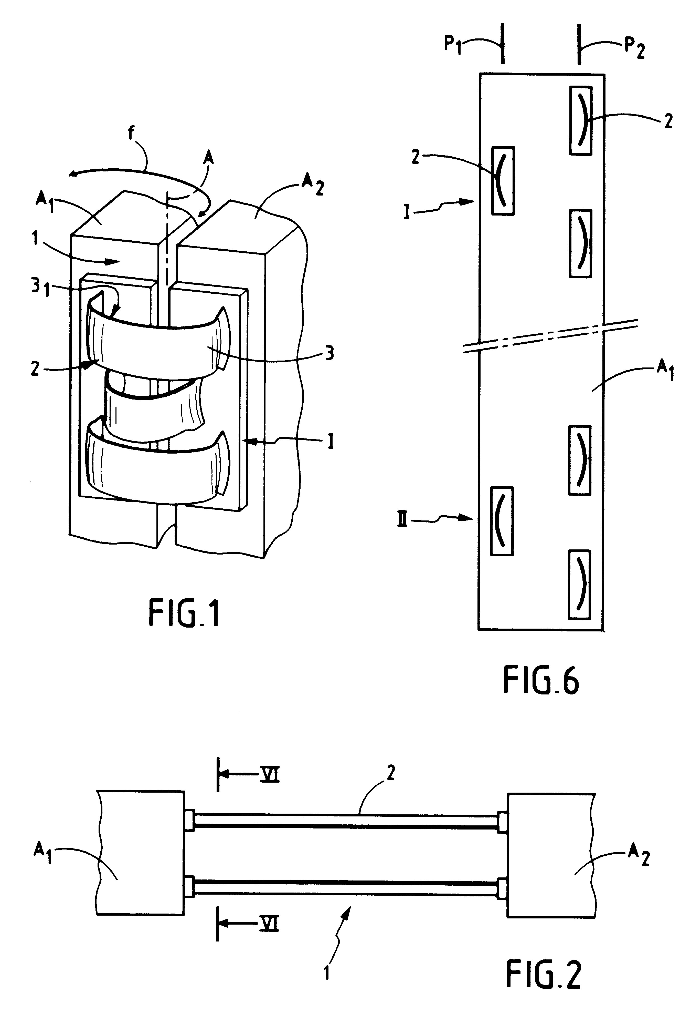
FIGS. 1 and 2 show an embodiment of a hinge 1 of the invention designed to be mounted between two adjacent elements or parts A.sub.1 and A.sub.2 of any kind and of appropriate shape. The hinge 1 is designed to go from a "folded" position shown in FIG. 1 to a "deployed" position shown in FIG. 2, thus enabling the parts A.sub.1 and A.sub.2 to be moved relative to each other through 180.degree. about a pivot axis A. In the example shown in FIGS. 1 and 2, the hinge 1 is made up of a series of hinge straps 2 of the invention that provide a self-driving function, a self-locking function, and a damping function.
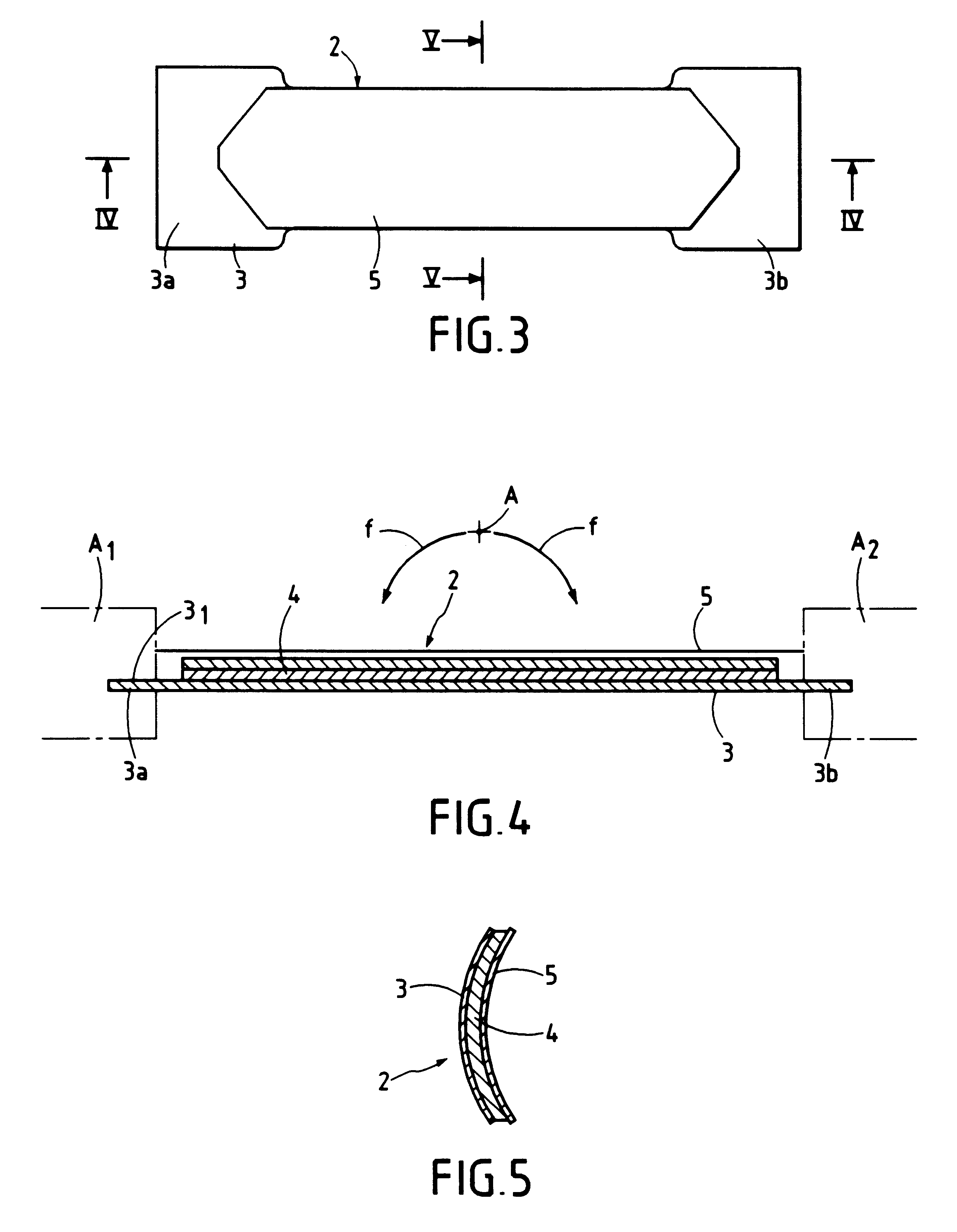
As can be seen more clearly from FIGS. 3 to 5, each hinge strap 2 comprises a resilient strip 3 that is preformed to have a right cross-section that is curved. For example, the resilient strip can be made from a metal tape having a right cross-section that is in the form of a circular arc. At rest or in the locking position, each resilient strip 3 occupies a rectilinear position wit...
PUM
 Abstract
Description
Claims
Application Information
 - R&D
- Intellectual Property
- Life Sciences
- Materials
- Tech Scout
- Unparalleled Data Quality
- Higher Quality Content
- 60% Fewer Hallucinations
Browse by: Latest US Patents, China's latest patents, Technical Efficacy Thesaurus, Application Domain, Technology Topic, Popular Technical Reports.
© 2025 PatSnap. All rights reserved.Legal|Privacy policy|Modern Slavery Act Transparency Statement|Sitemap|About US| Contact US: help@patsnap.com


