Placing an orthodontic element on a tooth surface

a technology for placing an orthodontic element and a tooth surface, which is applied in the field of positioning an orthodontic element on the surface of a tooth, can solve the problems of not having a method which will allow the correct positioning of the bracket on the tooth surface, and the difficulty of properly positioning the bracket on the lingual surfa

Inactive Publication Date: 2002-01-01
ALIGN TECH
View PDF6 Cites 87 Cited by
  • Summary
  • Abstract
  • Description
  • Claims
  • Application Information

AI Technical Summary

Benefits of technology

A preferred embodiment of the invention, which will be illustrated in more detail below, concerns the case where the real-life image centers on the orthodontic element or the marking member, in which case the real-life image thereof is continuously displayed in a fixed position of the display. A particularly preferred embodiment of the invention is such where the image capturing unit is mounted on the positioning device of the orthodontic element or of the marking member, thus having the orthodontic element or the marking member (as the case may be) in a fixed position of its field of view. It should however be noted that it is possible also to achieve the same effect namely displaying the real-life image of the orthodontic element on the display in a fixed position and orientation, by other means: for example, a stationary image capturing unit having the element in its field of view captures the image of the orthodontic element or the marking member and then by various rapid (real-time) image processing algorithms the orthodontic element or the marking member may always appears in defined spot of the display. For this purpose the image processing software may identify the element or the marking member by its contours. by its color or reflectiveness, by other clues, e.g. markings displayed thereon, etc.

Problems solved by technology

However, there is currently no available method which will allow to position the bracket correctly on a tooth surface, based on a determination made previously, e.g. based on a model.
However, by current methods it is difficult to properly position the brackets on the lingual surfaces, particularly in view of difficulties in monitoring the position during attachment of the brackets.

Method used


Image

  • Placing an orthodontic element on a tooth surface
  • Placing an orthodontic element on a tooth surface
  • Placing an orthodontic element on a tooth surface

Examples


Embodiment Construction

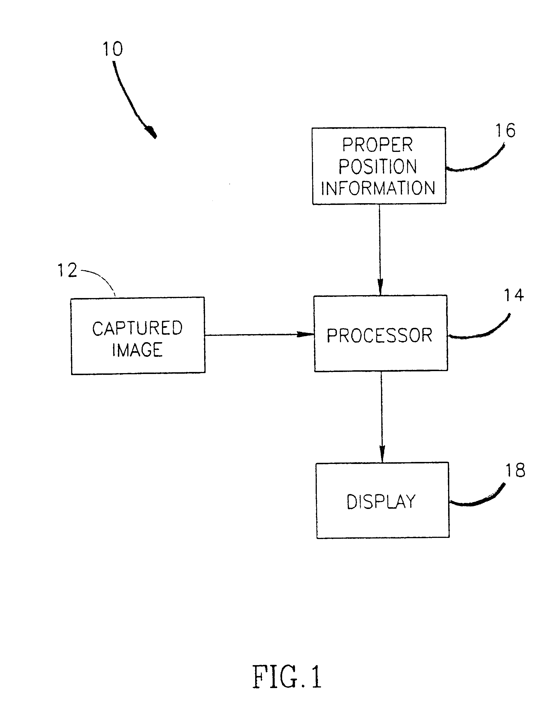
Reference is first being made to FIG. 1 showing the general scheme of a system 10 in accordance with an embodiment of the invention. An image 12 captured by an image acquisition unit is transmitted comprising the first unit 12 which comprises a camera to a processor 14 which also receives proper position information 16 and transmits both to display screen 16, e.g. a television screen, a computer monitor screen, etc. The image displayed on the screen may be captured by the image ("real life image") and may be an image displaying the proper position information, or a superimposition of both one on the other.

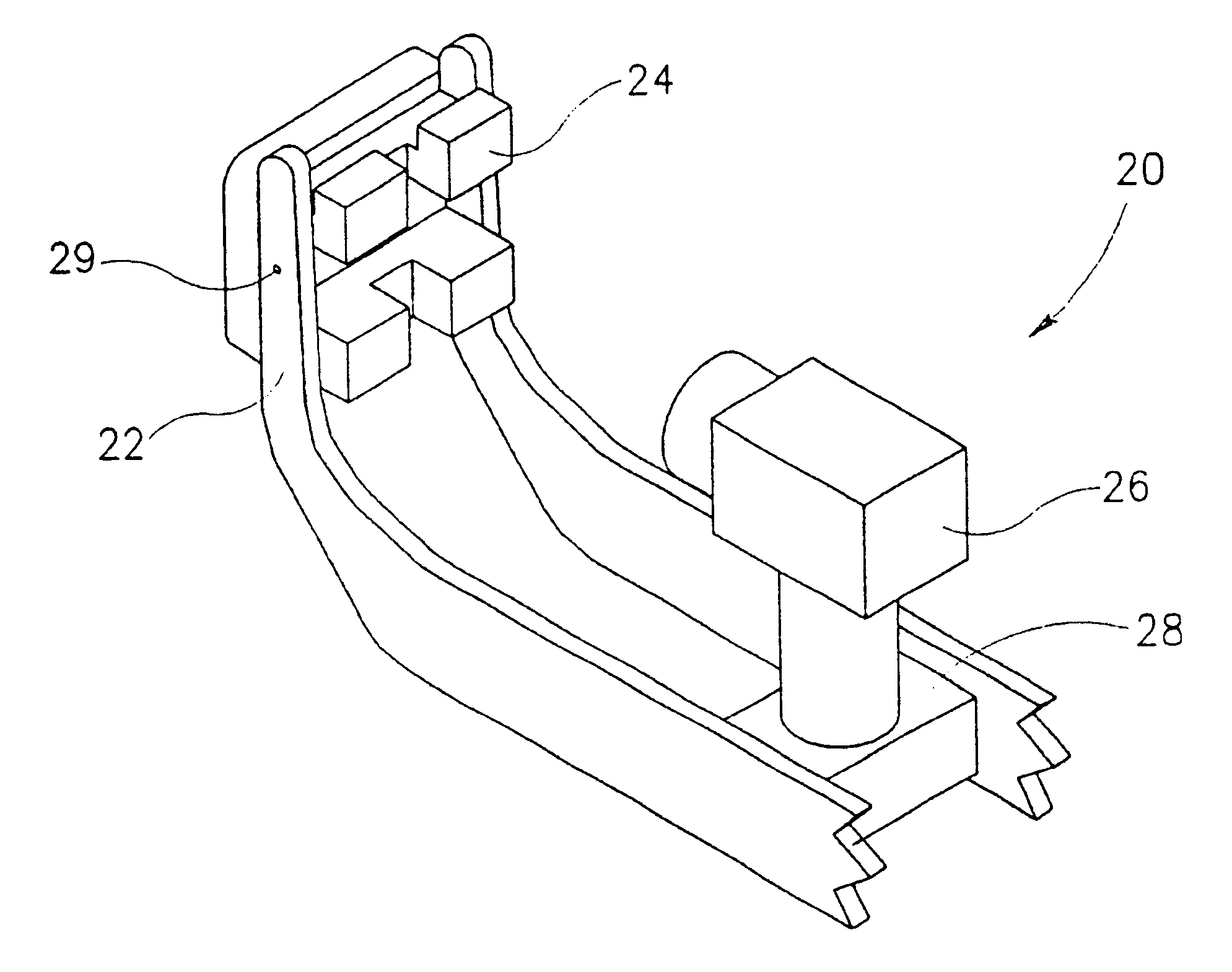
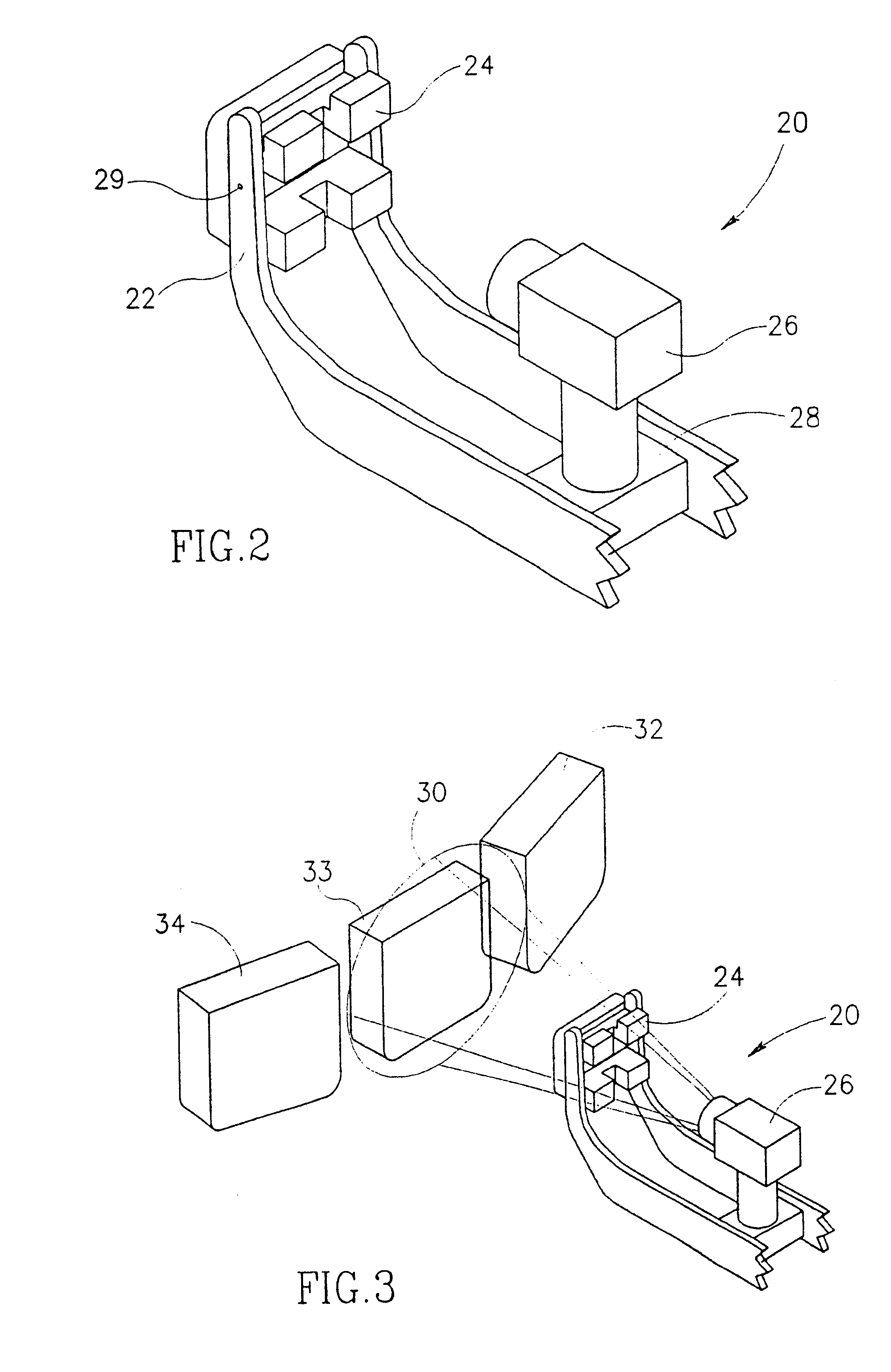
A bracket-positioning device 20 in accordance with an embodiment of the invention is shown in FIG. 2. This device, of which only the front part is shown (the rear part where the device may be held by the orthodontist is not shown) comprises bracket grippers 22, holding a bracket 24, a video camera 26, mounted on a mount 28 integral with bracket gripper 22. Bracket 24 may be fixed a...


PUM


Abstract

A method, system and device for positioning and fixing an orthodontic element on a surface of a tooth are provided. The positioning of the element on a tooth is accomplished by: bringing the element into proximity of the tooth while continuously capturing an image of at least the tooth or of the element, and an image of both, once the tooth and the element are proximal to one another; transmitting the image or its representation to a display for displaying a real-life image of the captured image or representation together with indicators providing guidance information on intended position of the orthodontic element on the tooth's surface; positioning the element on a tooth's surface according to said indicators such that the element's position coincides with the intended position; and fixing the element onto the tooth.

Description

FIELD AND BACKGROUND OF THE INVENTIONThe present invention is generally in the field of orthodontics and provides a method, system and device for placing an orthodontic element. e.g. a bracket on the surface of a tooth of an individual undergoing orthodontic treatment or for marking the spot on a tooth where such an element should be placed.One of the most critical steps in an orthodontic treatment is the proper placement of brackets on surfaces of teeth of treated individuals. The location of the bracket on the tooth as well as its orientation is a critical factor in determining the direction of movement of the teeth during the treatment. In current orthodontic practice, the orthodontist decides on a general scheme of placing the brackets on the teeth and then attaches each of them to the surface of a tooth, in an exact location and orientation decided at the time of such placing. Preparatory to an orthodontic treatment, the orthodontist typically prepares a plaster model of the te...

Claims


Application Information

Patent Timeline
Patent Type & Authority Patents(United States)
IPC IPC(8): A61C7/00A61C7/14A61C9/00
CPCA61C7/146A61C7/002A61C9/004A61C9/0053
Inventor TAUB, ELDADNISSENBAUM, BARUCHKOPELMAN, AVI
Owner ALIGN TECH
Why Eureka
Try Eureka