Blowing head including a buckle detector

a technology of blowing head and detector, applied in the field of blowing head, can solve problems such as delays in the installation process

Inactive Publication Date: 2002-04-02
BRITISH TELECOMM PLC
View PDF82 Cites 59 Cited by
  • Summary
  • Abstract
  • Description
  • Claims
  • Application Information

AI Technical Summary

Problems solved by technology

Buckling can cause the cable to jam in the duct and tends to cause delays in the installation process.

Method used


Image

  • Blowing head including a buckle detector
  • Blowing head including a buckle detector
  • Blowing head including a buckle detector

Examples


first embodiment

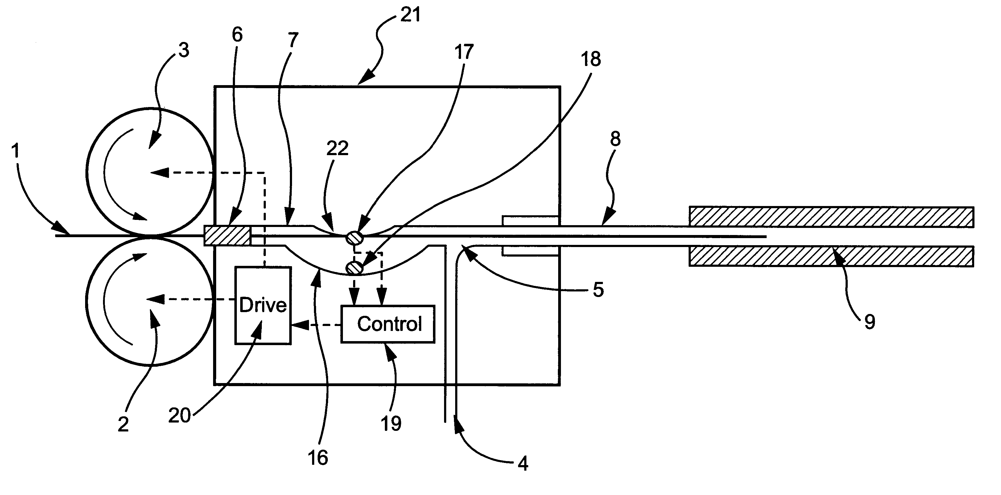
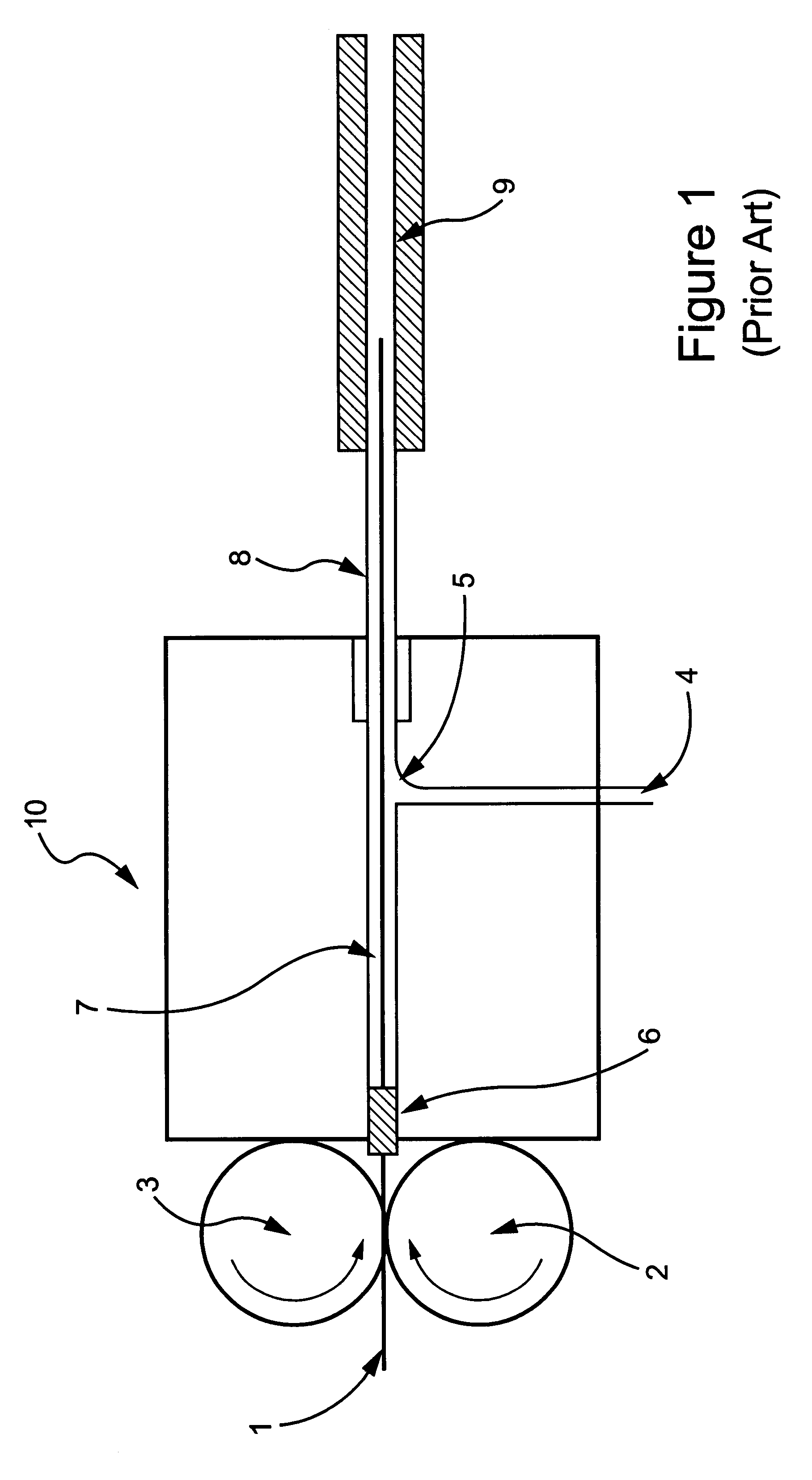
FIG. 3 shows a schematic depiction of the present invention. Blowing head 15 has many features common to the blowing head of the prior art such as the drive wheels 2 and 3, which drive the transmission line 1 through the seal 6 and along the passageway 7. The passageway 7 is, in use, at a pressure greater than the external pressure due to the supply of a high-pressure gaseous medium to the inlet 4, the high-pressure gas being introduced into the passageway 7 at the injection point 5. The outlet of the blowing head 15 is connected, via tube 8, to pre-installed duct 9 along which the transmission line 1 is propelled by the combination of the drive forces applied by the drive wheels 2 and 3 and the drag forces caused by the high-speed flow of the gaseous medium. Additionally there is a cavity 16 which adjoins the passageway intermediate the seal 6 and the gas injection point 5. The cavity 16 extends the cross-section of the passageway throughout the length of the cavity 16. Optical sen...

second embodiment

FIG. 10 shows a schematic perspective representation of a blowing head 21 according to the invention. The two halves of the blowing head 21 are connected by hinge 29 and can be fastened shut using clamp 30. It is understood that any other method of effecting a seal by fastening the two halves of the blowing head 21 together may be used, but the use of an integral hinge has the advantage of reducing the numbers of fasteners needed for a secure fixing of the upper and lower parts of the head, reducing the time involved in opening and closing the head. Also, the hinged arrangement lessens the likelihood of damage to seal 31 or the lower face of the upper half of the head. Seals 6 and 31 prevent the high-pressure gas escaping from the blowing head. Outlet 28 enables ducts of two different sizes to be sealingly clamped to the blowing head 21. Typically, circumferential grooves in the form of teeth are provided to facilitate the retention of the duct within the head are provided. Those sk...


PUM


Abstract

A blowing head for a blown fibre installation, the blowing head including a buckling detector in the transmission line being installed and decreasing the drive forces applied to the transmission line, preventing mechanical damage occurring to the transmission line.

Description

1. Field of the InventionThis invention relates to a blowing head for use in blown cable installations and to a buckle detector suitable for integration with such a blowing head.2. Related ArtIt is well known from European Patent EP-B-108590 and subsequent publications that optical fibre transmission lines can be installed into ducts using the fluid drag provided by a high-speed flow of a gaseous medium. This method is practiced with optical fibre and copper cables ranging in size from about 1 mm to 20 mm or more, depending upon the application and the route into which installation is to take place.As described in EP-B-108590 a blowing head comprises a pair of motor driven wheels which provide a propulsive force which serves to advance the cable until a sufficient length has been installed in the duct for viscous drag forces to be effective in further installing the cable (typically the first third to half of the overall length of the installation duct). The drive wheels also enable...

Claims


Application Information

Patent Timeline
Patent Type & Authority Patents(United States)
IPC IPC(8): G02B6/44H02G1/08G02B6/46
CPCH02G1/086G02B6/4464G02B6/52
Inventor BARKER, PHILIP A
Owner BRITISH TELECOMM PLC
Why Eureka
Try Eureka