Rail fastening system constructed to allow pre-assembly of a rail clip and shoulder

Inactive Publication Date: 2002-04-09
PROGRESS RAIL SERVICES
View PDF40 Cites 31 Cited by
  • Summary
  • Abstract
  • Description
  • Claims
  • Application Information

AI Technical Summary

Problems solved by technology

This process requires a large labor force and considerable time to place the components into a working position.
Accordingly, the handling and application of the loose rail fastening components typically comprises a significant part of the overall cost of the installati

Method used


Image

  • Rail fastening system constructed to allow pre-assembly of a rail clip and shoulder
  • Rail fastening system constructed to allow pre-assembly of a rail clip and shoulder
  • Rail fastening system constructed to allow pre-assembly of a rail clip and shoulder

Examples


Embodiment Construction

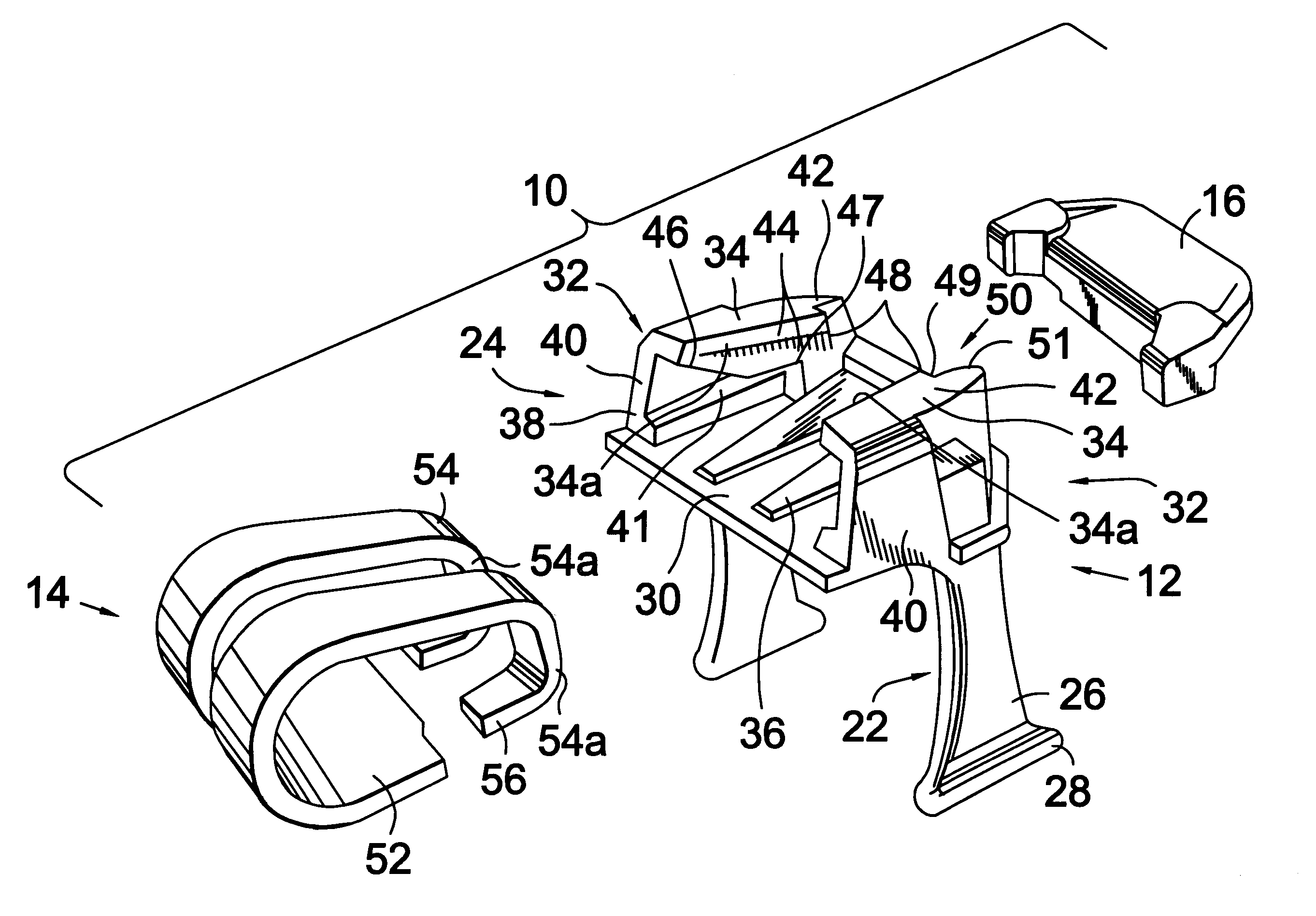
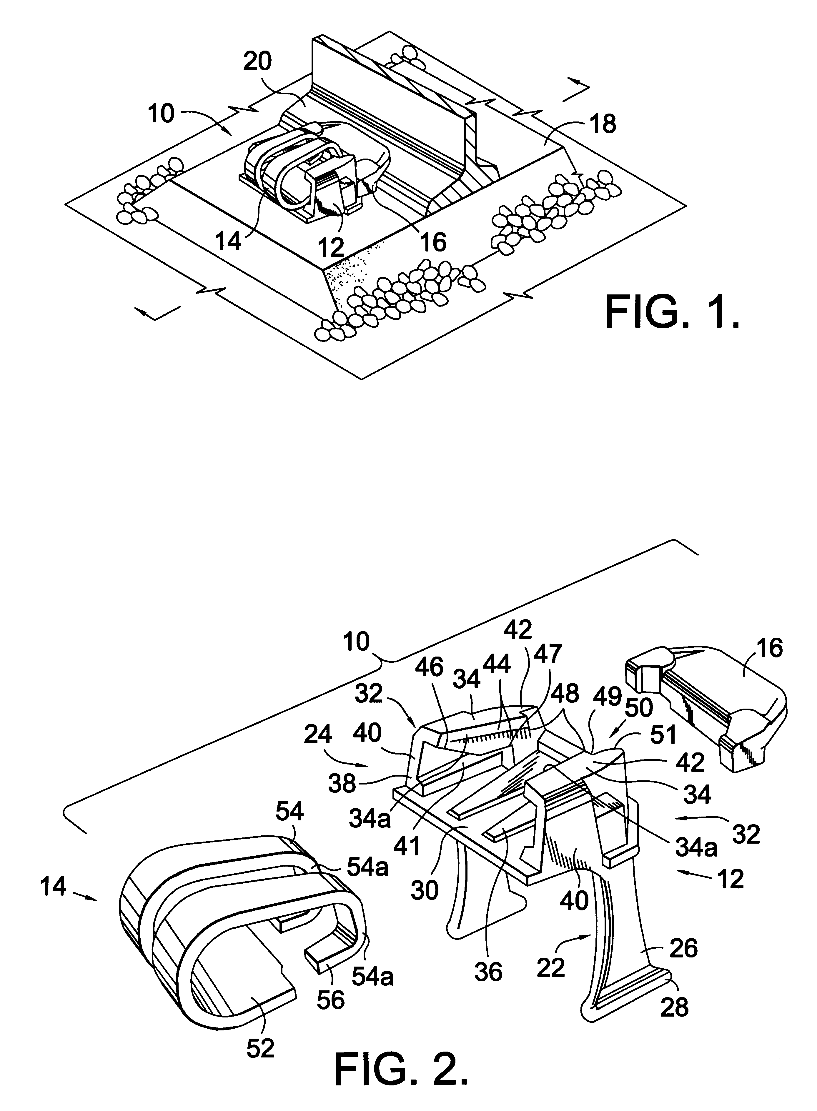
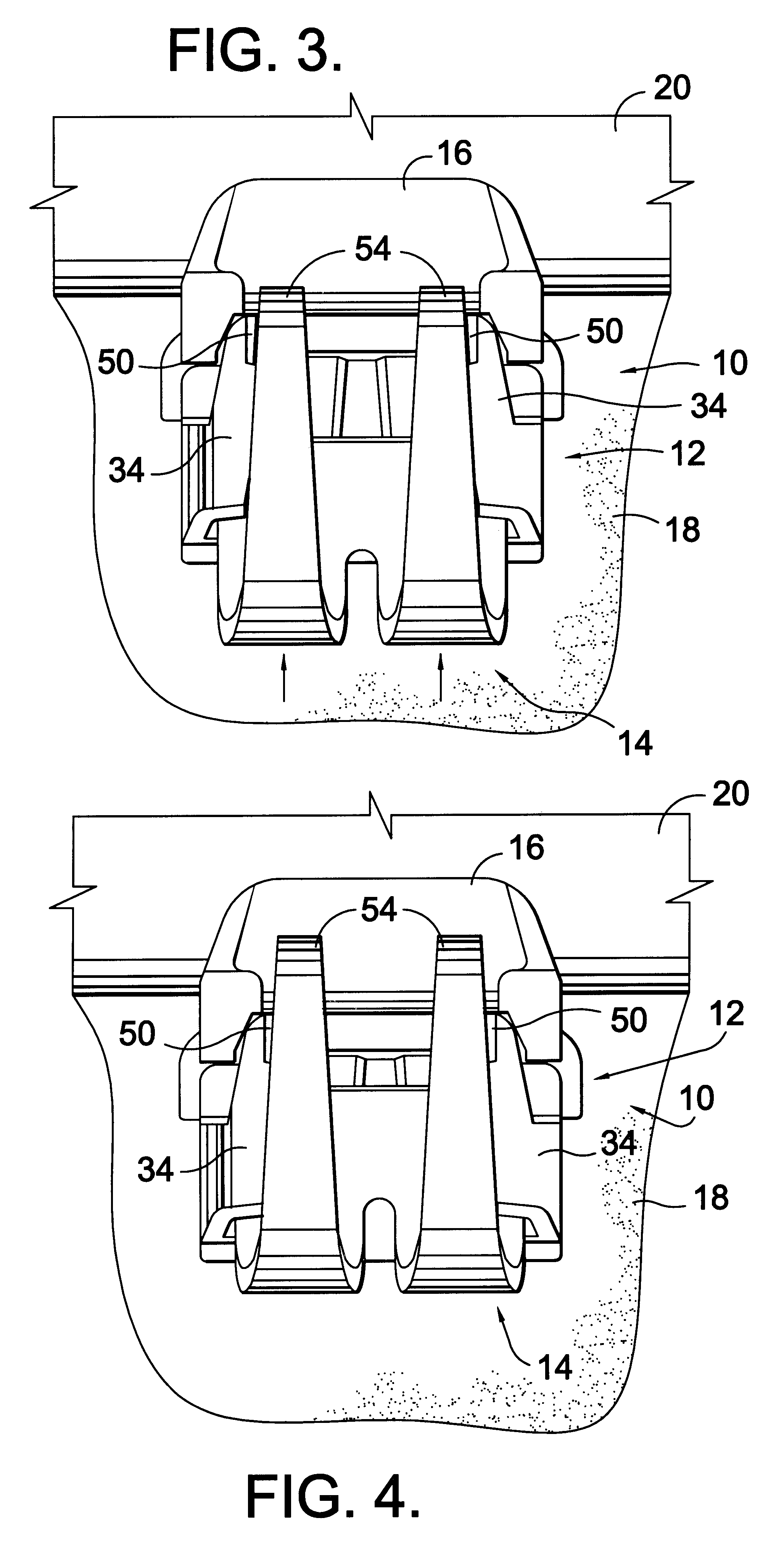
FIG. 1 illustrates a rail fastening system constructed according to the present invention and denoted generally by the reference numeral 10. System 10 includes a cast shoulder 12, an elastic rail spring clip 14, and an insulator 16. When applied to a railroad tie 18, which is preferably made of concrete or similar material, system 10 secures a railroad rail 20 to the tie 18. Preferably, two of the rail fastening systems 10 are used for each tie 18 on each rail 20, with one fastening system on the field side of each rail and another fastening system on the gauge side of each rail. The ties 18 are spaced apart and extend transversely to the rails 20 in the usual manner.

With reference to FIG. 2, the cast shoulder 12 of the present invention includes an anchoring portion 22 and a receiving portion 24. Anchoring portion 22 preferably includes two vertically extending legs 26 having flared lower ends 28 for attachment with concrete railroad tie 18. Preferably, the legs 26 are embedded in ...


PUM


Abstract

A rail fastening system including a cast shoulder and an elastic rail spring clip for applying a holding force to an insulator and a rail. The spring clip includes a pair of compressible arms for exerting a rail hold down force and a substantially horizontal base portion for application to the cast shoulder. The cast shoulder includes an anchoring portion, a receiving portion including converging opposing sides angled to define a throat having a width less than a decompressed width of the spring clip arms, and notches on the sides adjacent to the throat. In practice, the spring clip is applied to the cast shoulder such that two spring clip arms contact and move along the converging sides causing the spring clip arms to be compressed by the sides. When the arms move beyond the throat, the arms spring outwardly into the notch. The notch provides a catch that prevents any backward migration such that the elastic rail spring clip and the cast shoulder can be pre-assembled at a remote location, requiring less labor at the rail installation site.

Description

1. Field of the InventionIn general, this invention relates to a rail fastening system, and in particular, to a method and device for securing a rail to a concrete rail tie.2. Description of the Related ArtConventional fastening systems for concrete rail ties generally have a cast shoulder, an elastic rail spring clip, and a rail insulator. In this conventional system, the tie is formed with a portion of the cast shoulder imbedded into the tie. To secure the rail to the tie, the elastic rail spring clip is applied to the cast shoulder such that spring arms of the elastic spring clip press the insulator downwardly against a top portion of the rail flange to exert a rail hold down force. At the same time, the body or base of the elastic rail spring clip is secured to the cast shoulder to prevent movement of the rail flange.This conventional system requires the loose components such as the insulator and the elastic rail spring clip to be wholly installed at the construction site. This ...

Claims


Application Information

Patent Timeline
IPC IPC(8): E01B9/00E01B9/30
CPCE01B9/306
Inventor MEDIAVILLA, JOSE
Owner PROGRESS RAIL SERVICES
Why Eureka
Try Eureka