
Insulating units

a technology of sealing insulating and unit, which is applied in the direction of building components, constructions, buildings, etc., can solve the problems of increased moisture content of the gas between the panes, replacement of the unit, and longer li

Inactive Publication Date: 2002-04-16
PILKINGTON GROUP LTD
View PDF58 Cites 44 Cited by
  • Summary
  • Abstract
  • Description
  • Claims
  • Application Information

AI Technical Summary

Benefits of technology

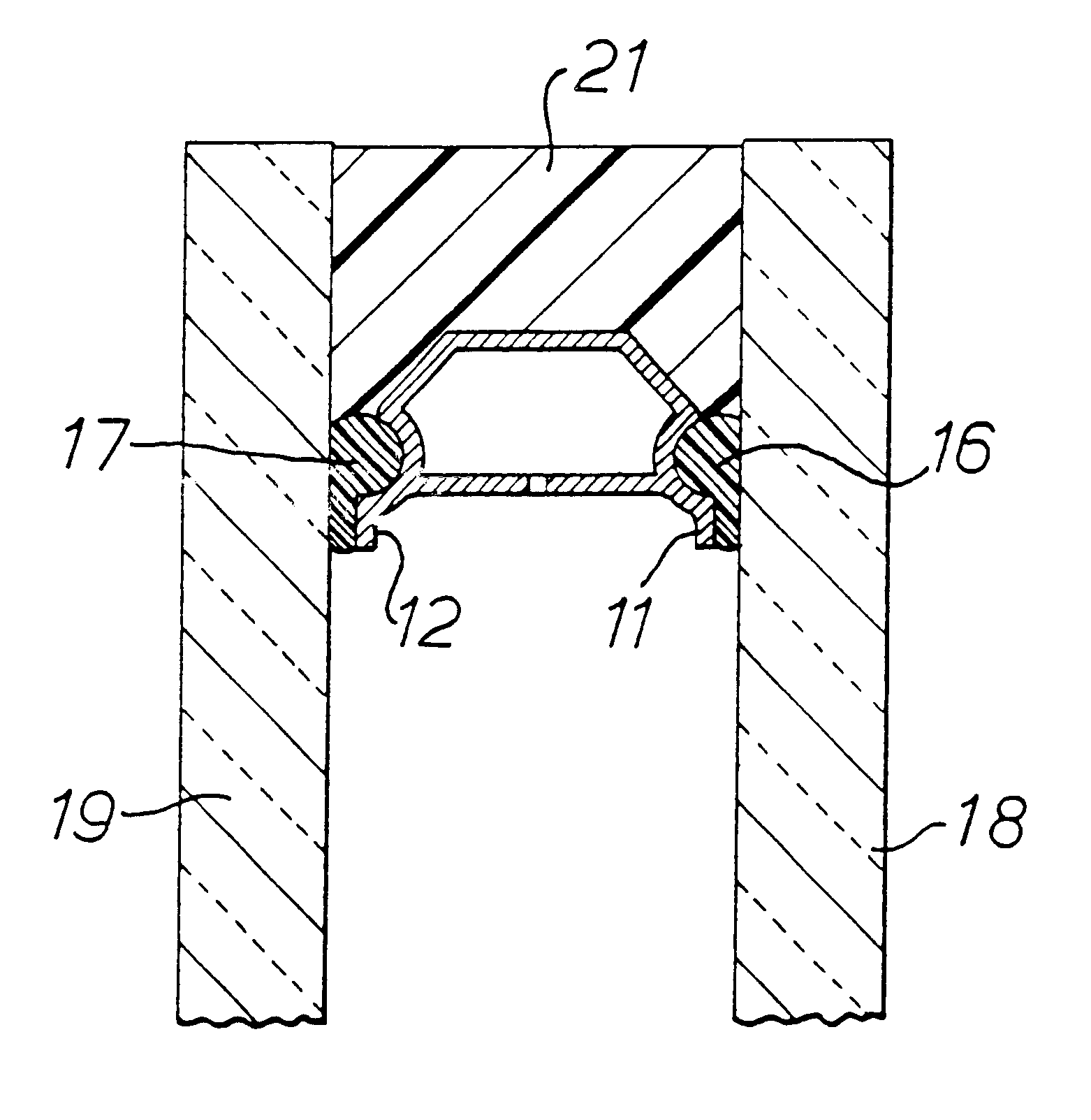
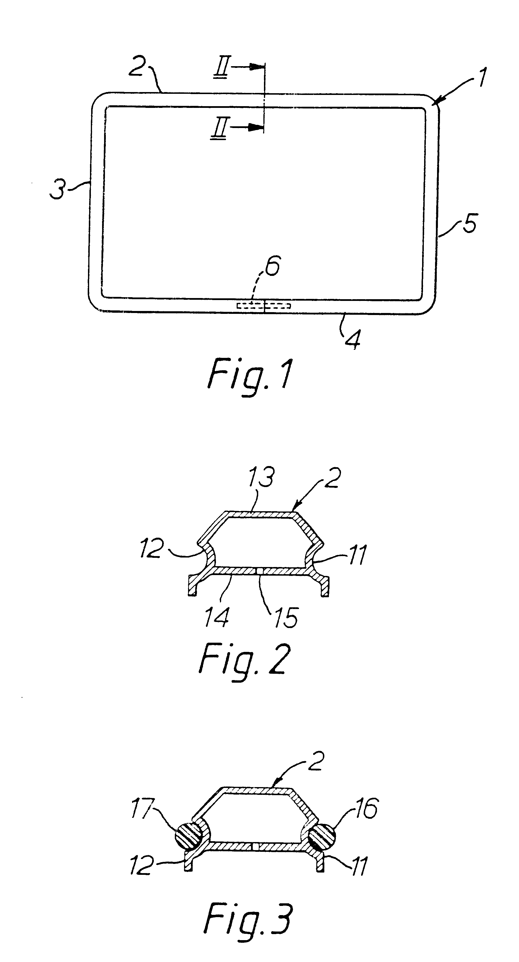
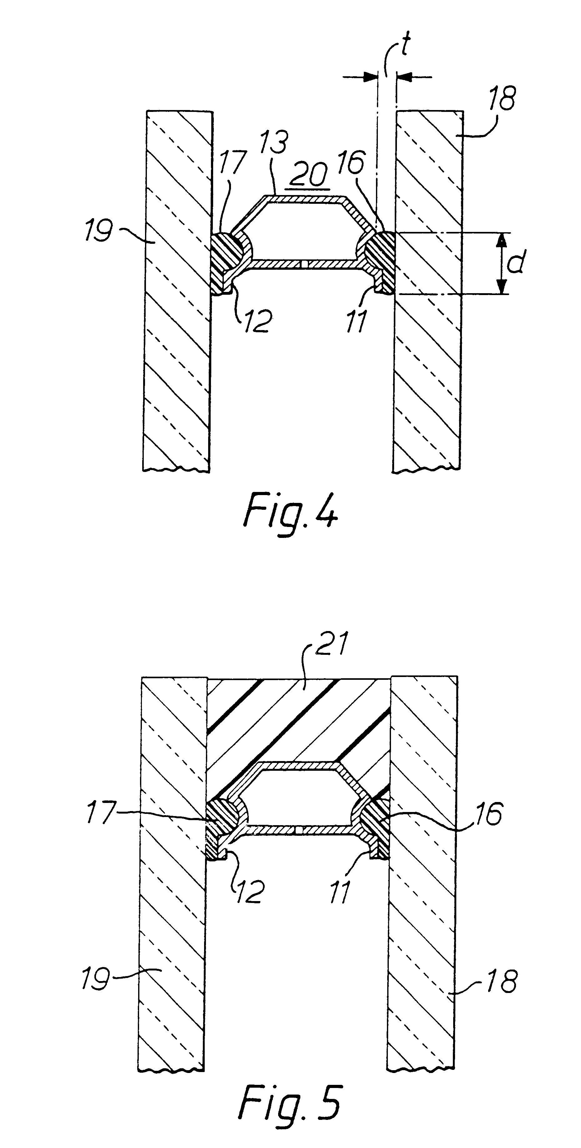
According to a third aspect of the invention, there is provided the use, in a twin seal sealed insulating unit, of a primary seal between each side of a spacer frame and the adjacent opposing pane having a thickness of greater than 0.4 mm on construction of the unit, to extend the reliable lifetime of the unit. In these second and third aspects of the invention, the amount of primary seal material is preferably, but not necessarily, at least 7 grams on each side of the spacer frame per meter of spacer length.

Problems solved by technology

Eventually, however, the drying agents become saturated and unable to absorb further moisture so that the moisture content of the gas between the panes increases and water vapour condenses on an internal pane surface; such condensation detracts from the appearance of the unit generally being regarded as amounting to failure of the unit and requiring replacement of the unit.
There is demand for units with a longer lifetime, but manufacturers are reluctant to offer guarantees as they have been unable to produce units which provide consistently longer lifetimes.
Hitherto, premature failures have generally been associated with poor unit construction, for example, insufficient to poorly mixed secondary sealant, or insufficiently cleaned panes resulting in poor adhesion to the glass, and attempts to provide more reliable and consistent unit lifetimes have generally concentrated on avoiding such construction deficiences.
Moreover, since the only path for ingress of moisture vapour into the gas space of the unit is between the sides of the spacer and the opposing pane surfaces it has been considered that a wider gap (corresponding to the thickness of the primary sealant) would lead to greater moisture ingress.
The inventors have discovered, however, that the use of a sealant thickness greater than 0.4 mm, preferably at least 0.5 mm, enables a consistently longer unit life to be achieved before the dew point is reached and the unit fails, with a much lower risk of premature failure.
In addition, the thicker primary seal tends to reduce the absorption of water therein which can lower the elastic modulus of the material which in turn can tend to cause failure of the primary seal.
In particular, when the glazing unit is subjected to an increase in temperature, this can cause an increase in the thickness of the unit at the sealed edge of the unit.

Method used


Image

  • Insulating units
  • Insulating units
  • Insulating units

Examples


example 2

The procedure of Example 1 was repeated using PRC (trade mark) 469 two part polysulphide as secondary sealant in place of the Dow Corning silicone sealant. As in Example 1, all 10 units maintained a dew point below -50.degree. C. for over 700 cycles. After 728 cycles, one unit was dropped and removed from test. After 868 cycles, the dew point of one unit had risen to a temperature in the range -49.degree. C. to -40.degree. C.: the dew point of this unit increased to above 0.degree. C. (unit failure) after 1004 cycles, with the remaining units maintaining dew points below -50.degree. C. to 1004 cycles whereupon testing was terminated.

The thickness measurements showed similar trends to those observed in Example 1, except that the maximum thicknesses were observed somewhat later in the test procedure and the thicknesses increased at the mid points of the edges declined to substantially zero thereafter, with an overall negative increase i.e. a reduction on the original thickness, being ...

example 3

The procedure of Example 2 was repeated using PRC (trade mark) 449 two part polysulphide as secondary sealant in place of the PRC 469 used in Example 2; the PRC 449 has a higher modulus than PRC 469. All 10 test units maintained a dew point below -50.degree. C. for over 1000 cycles, when testing was terminated.

The thickness measurements again showed a general increase in thickness. Initially, this was greatest at the mid points of the long edges (around 1 mm after 150 cycles) and least at the mid points of the short edges (around 0.5 mm after 150 cycles) with an intermediate value at the corners. However, as the testing continued, the thickness increased to over 1 mm at the corners after approximately 800 cycles, substantially equal, increases at the mid points of the long and short edges.


PUM

PropertyMeasurementUnit
lengthaaaaaaaaaa
internal radiusaaaaaaaaaa
thickaaaaaaaaaa

Abstract

A sealed insulating unit includes two parallel opposed panes with a spacing and sealing system between the two panes. The panes and the spacing and sealing system together define a sealed gas space. The spacing and sealing system includes a spacer frame with a primary seal between each side of the spacer frame and the opposing pane face and a secondary seal extending between the panes outside the outer peripheral face of the spacer frame. Each primary seal is greater than 0.4 mm thick on construction of the unit and has at least 7 grams of sealant material on each side of the spacer frame per meter of the spacer frame length. A spacer for a sealed insulating unit has side walls in which are defined elongate recesses, the dimensions of the recesses being selected such that sufficient primary sealant can be accommodated to provide in the sealed insulating unit opposed primary seals each at least 0.4 mm thick.

Description

BACKGROUND TO THE INVENTIONThe present invention relates to sealed insulating units, especially but not exclusively sealed double glazing units, and, in particular, to a form of construction of sealing insulating units which provides an assured long lifetime, to a method of constructing sealed insulating units to achieve an assured long lifetime, and to the use of a thick primary seal to achieve such a lifetime. The present invention also relates to spacer frame constructions for such units.In a well known form of construction, a sealed double glazing unit comprises two parallel opposed panes of transparent or translucent glazing material, usually but not necessarily glass, with a spacing and sealing system therebetween defining, with the panes, a sealed gas space. The space usually contains air, but selected other gases may be used in place of air to enhance the thermal or acoustic insulating properties of the unit. The spacing and sealing system may comprise a spacer frame, common...

Claims


Application Information

Patent Timeline
Patent Type & Authority Patents(United States)
IPC IPC(8): E06B3/663E06B3/66C03C27/06
CPCE06B3/66352E06B3/66342
Inventor EVASON, JOHNDAVIES, MERVYN JOHNPEARSON, KENNETH JOHN
Owner PILKINGTON GROUP LTD
Learn More