Pulley assembly for liquid level gauging system

a technology of liquid level gauge and pulley, which is applied in the direction of level indicators with buoyant probes, friction gearings, and gearing, etc., can solve the problems of excessive wear of cable and/or pulley wheels, difficult and time-consuming adjustment of cable guidance means, etc., and achieves the effect of easily and securely fixing in the desired position and being easily positioned along the pulley hanger

Active Publication Date: 2021-05-18
SPENCER JOSHUA
View PDF2 Cites 0 Cited by
  • Summary
  • Abstract
  • Description
  • Claims
  • Application Information

AI Technical Summary

Benefits of technology

[0009]In accordance with the foregoing objects, the present invention—a pulley assembly for use in connection with a liquid level gauging system—generally comprises an elongate pulley hanger, supported at the upper end of a pillar rising from and dependently supported by a base bracket, and first and second pulleys slidingly supported by the pulley hanger. The base bracket securely mounts the pulley assembly to the top of a liquid storage tank. Each provided pulley comprises, or is otherwise provided with, a clamp, whereby each pulley is readily positioned along the pulley hanger, and, when in a desired position, easily and securely fixed in the desired position.
[0010]The cooperative arrangement of each pulley and clamp with the pulley hanger serves to ensure that each pulley is at all times maintained in alignment with the other pulley, such that a cable running between the pulleys will always oriented perpendicularly to the rotational axis of the pulley sheave. In this manner, wear on the cable and / or sheaves is minimized, thereby greatly increasing the reliable lifetime of the liquid level gauging system of which the pulley assembly is integral part.

Problems solved by technology

In particular, Applicant has in practice found that the cable guidance means as described by Clanton is difficult and time consuming to properly adjust, owing in at least some part to the placement of the pulleys within the interior space of the described encompassing frame members.
Additionally, the cable guidance means as described by Clanton fails to ensure that the first and second pulleys align one with the other, thus often resulting in excessive wear on the cable and / or pulley wheels.

Method used


Image

  • Pulley assembly for liquid level gauging system
  • Pulley assembly for liquid level gauging system
  • Pulley assembly for liquid level gauging system

Examples


Embodiment Construction

[0018]Although those of ordinary skill in the art will readily recognize many alternative embodiments, especially in light of the illustrations provided herein, this detailed description is exemplary of the preferred embodiment of the present invention, the scope of which is limited only by the claims appended hereto.

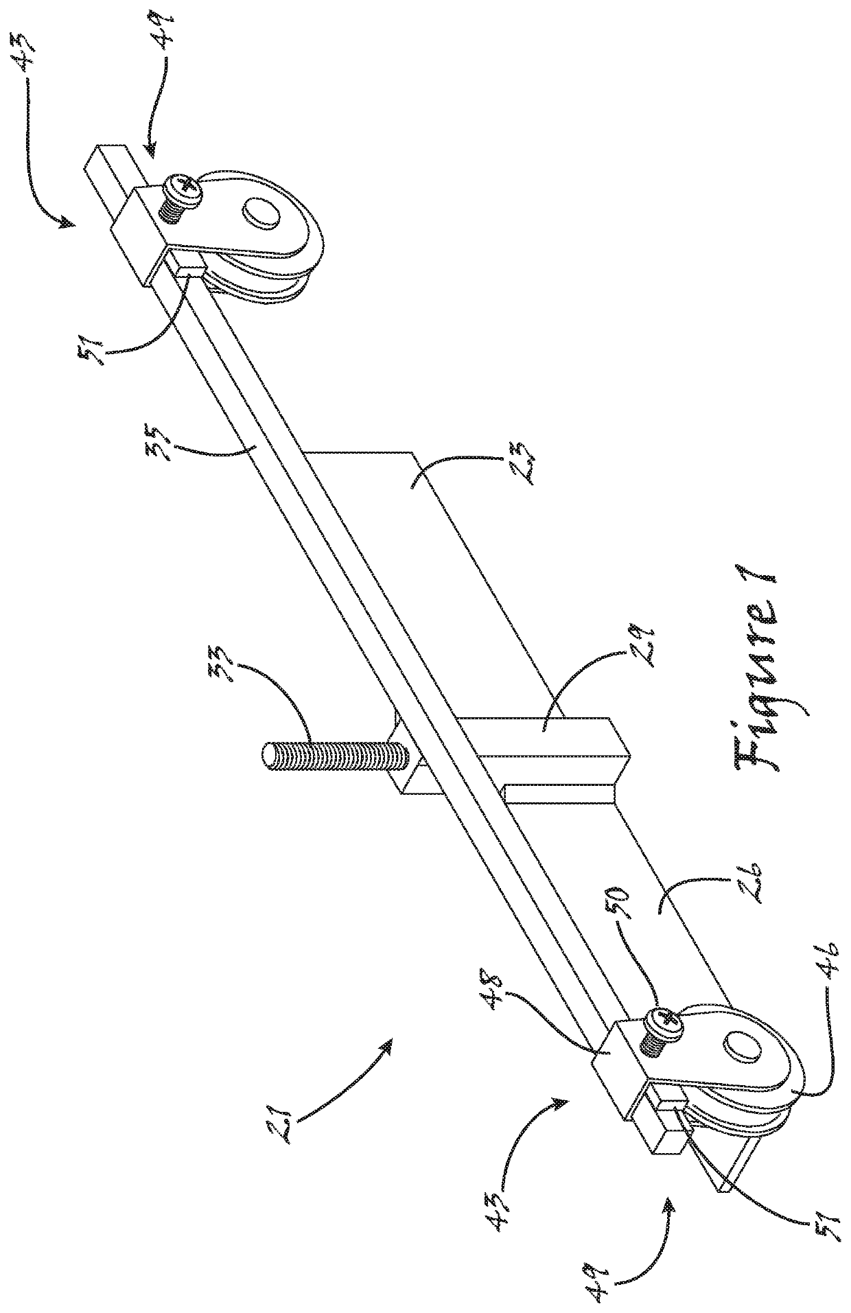
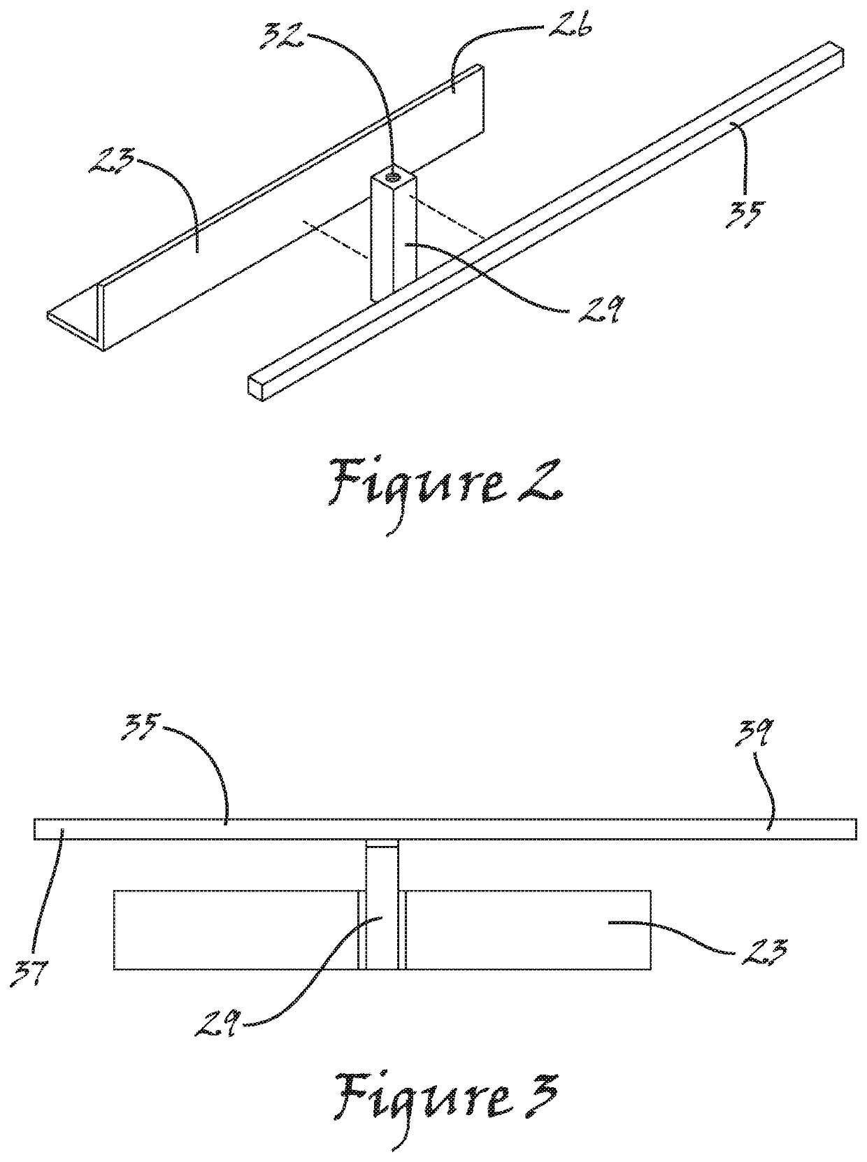
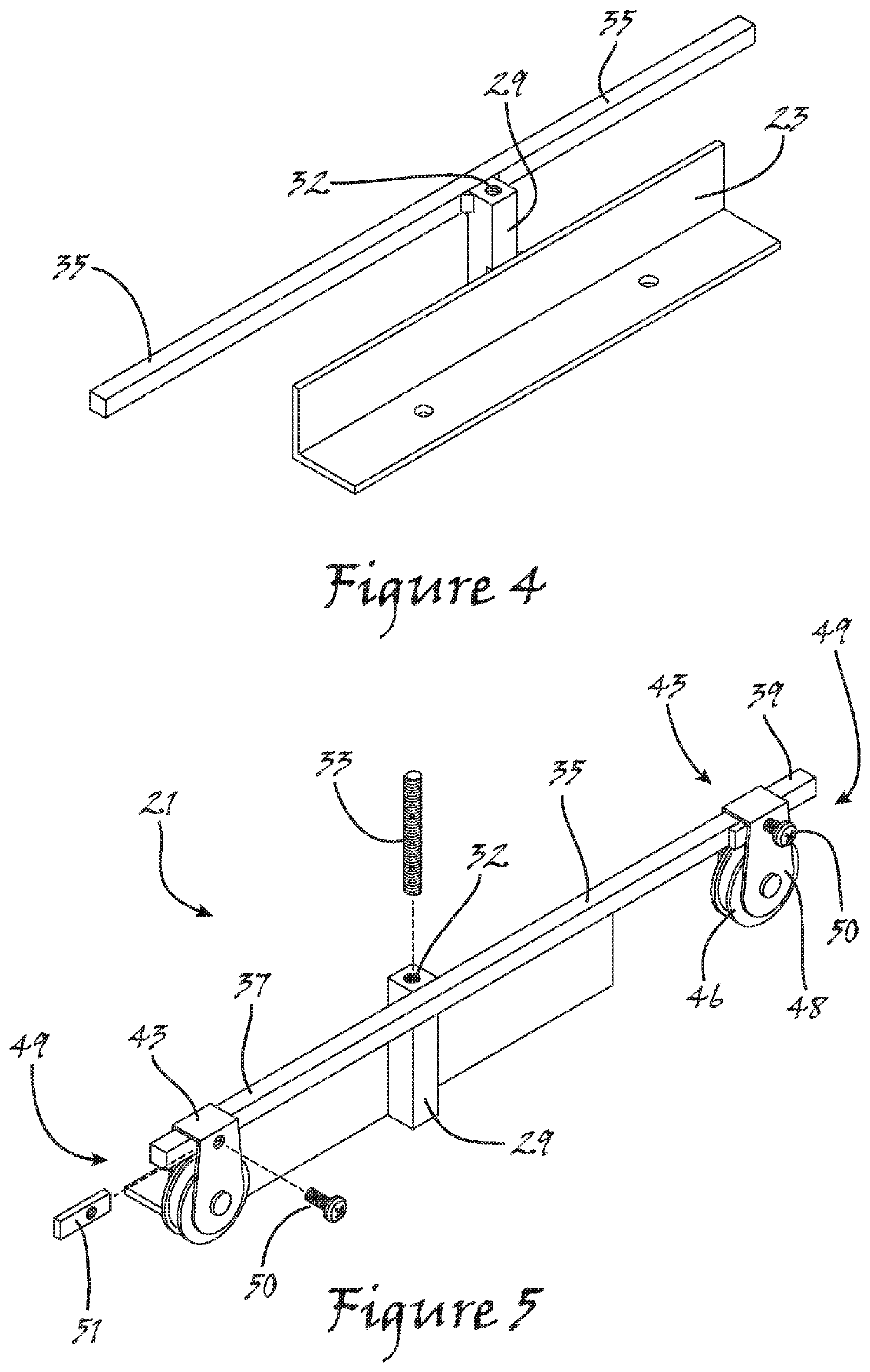
[0019]Referring now to the figures, and to FIG. 1 in particular, a preferred implementation of the pulley assembly 21 of the present invention is shown to generally comprise an elongate pulley hanger 35, which is dependently supported at the upper end of a pillar 29, which rises from, and is dependently supported by, a base bracket 23, and first and second pulleys 43 slidingly supported by the pulley hanger 35. The base bracket 23 is adapted to securely mount the pulley assembly 21 to the top of a liquid storage tank, and, to this end, is provided with a plurality of tank mounting holes 25, as particularly shown in FIG. 4. As will be better understood further herein, ea...


PUM


Abstract

A pulley assembly includes an elongate pulley hanger, supported at the upper end of a pillar rising from and dependently supported by a base bracket, and first and second pulleys slidingly supported by the pulley hanger. The base bracket securely mounts the pulley assembly to the top of a liquid storage tank. Each provided pulley implements, or is otherwise provided with, a clamp, whereby each pulley is readily positioned along the pulley hanger, and, when in a desired position, easily and securely fixed in the desired position.

Description

RELATED APPLICATION[0001]This present application claims, under 35 U.S.C. § 119(e), all available benefit of, and priority to, U.S. provisional patent application Ser. No. 62 / 444,186 filed Jan. 9, 2017. By this reference, the full disclosure, including the drawings, of U.S. provisional patent application Ser. No. 62 / 444,186 is incorporated herein, as though now set forth in its entirety.FIELD OF THE INVENTION[0002]The present invention relates to material handling. More particularly, the invention relates to an improved pulley assembly for use in connection with a gauging system whereby the level of a liquid contained within a storage tank may be readily ascertained.BACKGROUND OF THE INVENTION[0003]U.S. Pat. No. 7,353,704 issued Apr. 8, 2008 to Clanton (“Clanton”), which is incorporated herein as though now set forth in its entirety, discloses the use of a cable guidance means in the provision of an external liquid level gauge, which enables the level of a liquid contained within a ...

Claims


Application Information

Patent Timeline
Patent Type & Authority Patents(United States)
IPC IPC(8): F16H19/00G01F23/42F16H19/06G01F23/40F16H19/02
CPCF16H19/003F16H19/02F16H19/06F16H19/0622F16H19/0645G01F23/40G01F23/42G01F23/0038
Inventor SPENCER, JOSHUA
Owner SPENCER JOSHUA
Why Eureka
Try Eureka