
CPU core voltage switching circuit

a switching circuit and core voltage technology, applied in the direction of generating/distributing signals, process and machine control, instruments, etc., can solve the problem of inability to reduce power

Inactive Publication Date: 2002-05-14
RPX CORP
View PDF8 Cites 86 Cited by
  • Summary
  • Abstract
  • Description
  • Claims
  • Application Information

AI Technical Summary

Problems solved by technology

That is, the problems with the prior art reside in that, because the CPU core voltage (or the switching circuit thereof) requires a constant voltage, it is impossible to reduce power even when a slow CPU CLK (CPU clock pulse) is used or the load is reduced.

Method used


Image

  • CPU core voltage switching circuit
  • CPU core voltage switching circuit
  • CPU core voltage switching circuit

Examples


Embodiment Construction

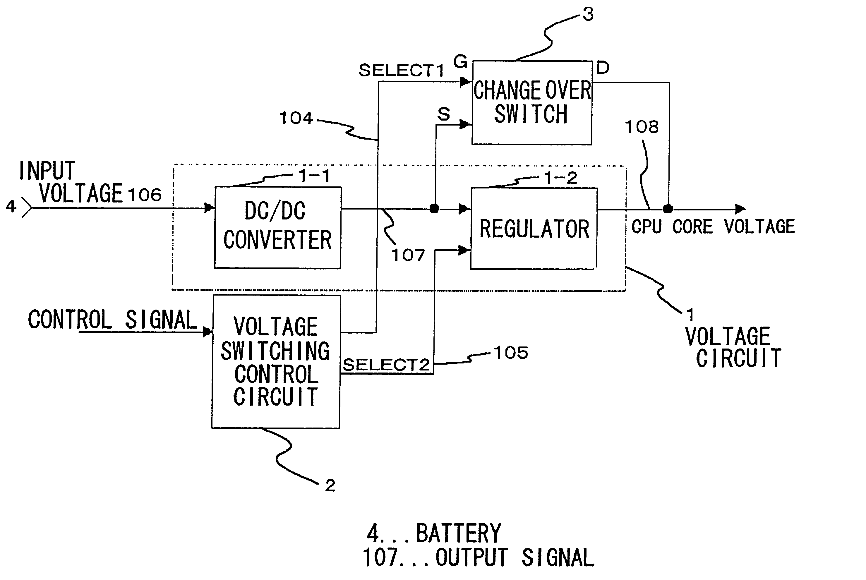
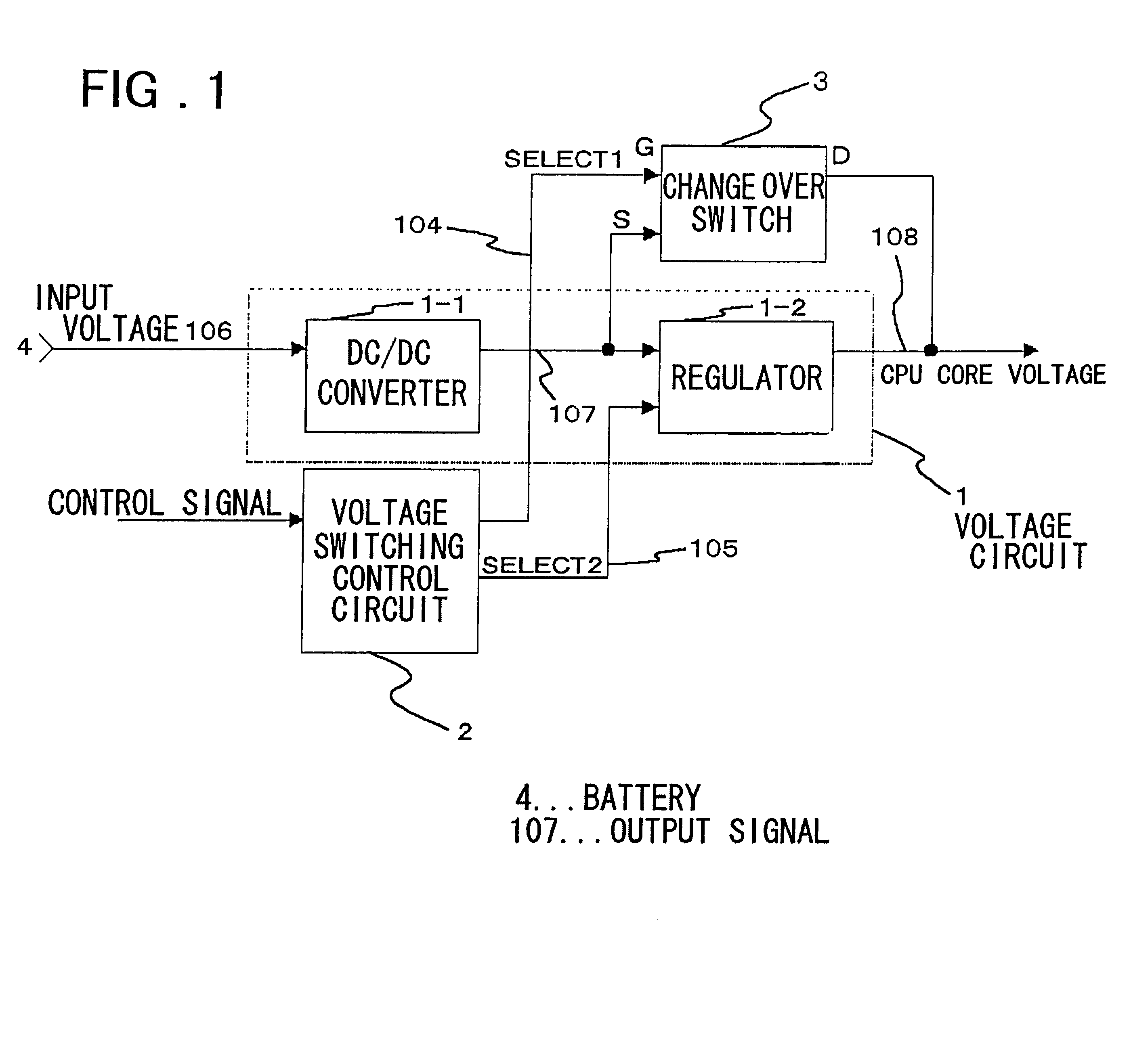
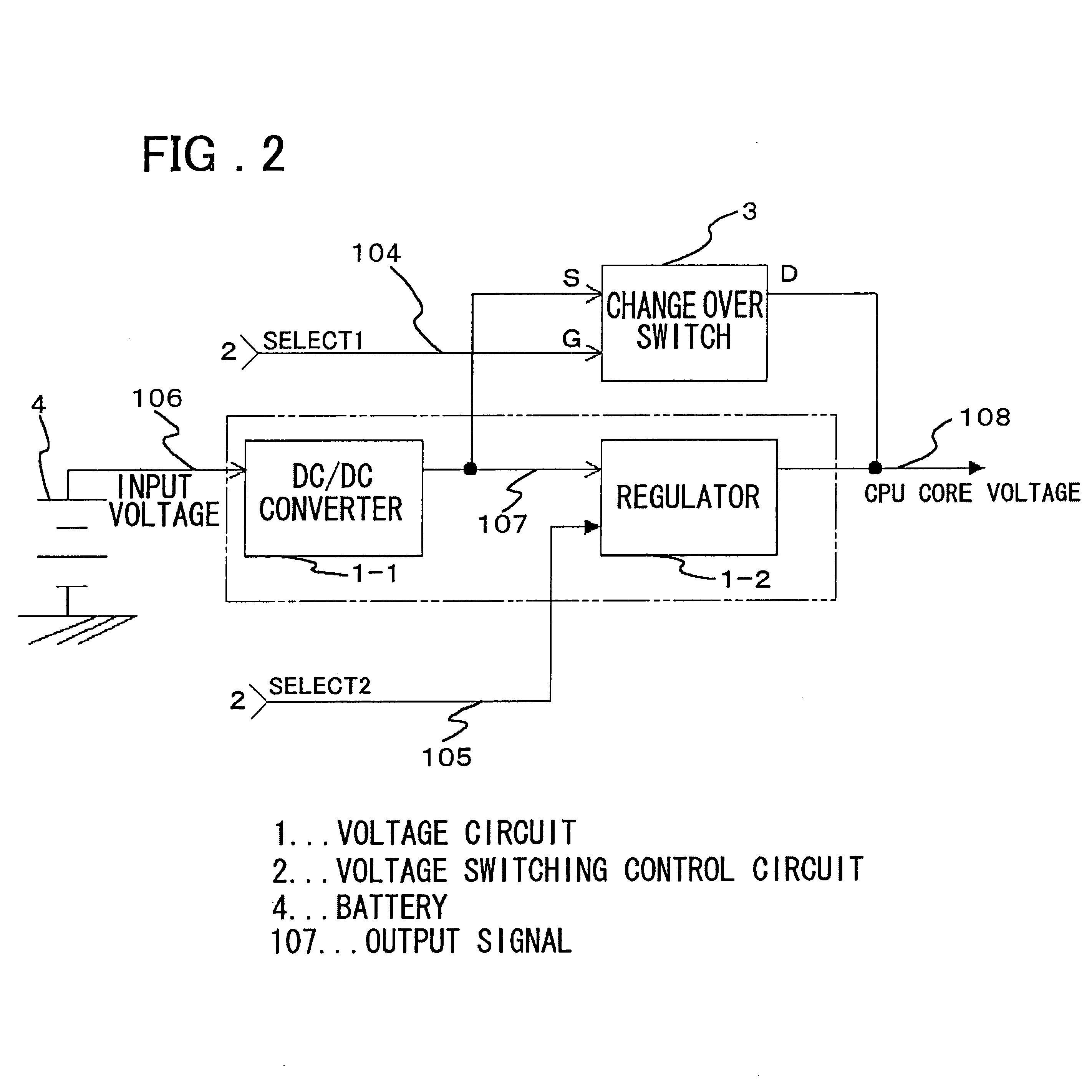
A CPU core voltage switching circuit according to the present invention drives an apparatus or terminal (such as a personal data assistant), in which a circuit according to the present invention is installed, at a first (high) CPU core voltage of 2.7 V when the apparatus or memory data is initialized, and at a second (low) CPU core voltage of 2.0 V when an application software product is used. More specifically, the circuit according to the present invention uses a first (high) frequency of f=33 MHz as a CPU CLK frequency to set the CPU core voltage to 2.7 V when an apparatus containing this circuit is initialized or memory data is initialized, a second (low) of frequency and f / 2=16.5 MHz as a CPU CLK frequency to set the CPU core voltage to 2.0 V when an application software product is executed.

In a voltage switching control circuit 2, which will be decried later, a voltage switch trigger signal (control signal that will be described later; SUSPEND signal) is controlled in advance ...


PUM


Abstract

A CPU core voltage switching circuit installed in a personal digital assistant wherein, when the personal digital assistant is using an application software product, a CPU clock frequency is reduced to a half of the frequency used when the personal digital assistant is in an initial start state or a memory data initialization state.

Description

The present invention relates to a CPU (Central Processing Unit) core voltage switching circuit for reducing the power consumption of a CPU.Conventionally, a CPU core voltage switching circuit, to which the present invention pertains, has been used primarily in reducing the power consumption of the CPU. With respect to such a CPU core voltage switching circuit, used recently in personal digital assistants (PDA), there is need to reduce power consumption in a terminal.SUMMARY OF THE DISCLOSUREConventionally, the CPU core voltage switching circuit used in a personal digital terminal (or assistant) requires a constant CPU core voltage.However, there are problems encountered in the course of investigations toward the present invention. That is, the problems with the prior art reside in that, because the CPU core voltage (or the switching circuit thereof) requires a constant voltage, it is impossible to reduce power even when a slow CPU CLK (CPU clock pulse) is used or the load is reduce...

Claims


Application Information

Patent Timeline
Patent Type & Authority Patents(United States)
IPC IPC(8): G06F1/32G05F1/40G05F1/10G06F15/76G06F15/78G06F1/04
CPCG06F1/324G06F1/3296Y02B60/1285Y02B60/1217Y02D10/00
Inventor UCHIDA, MASANOBU
Owner RPX CORP
Learn More