Box handling grip

a box and handle technology, applied in the field of box handling grips, can solve the problems of difficult handling of boxes, difficult handling of larger boxes, and difficulty in one person handling,

Inactive Publication Date: 2002-07-23
JORDENING HAROLD GENE
View PDF13 Cites 14 Cited by
  • Summary
  • Abstract
  • Description
  • Claims
  • Application Information

AI Technical Summary

Problems solved by technology

Such surfaces make them difficult to grasp for handling, especially if relatively heavy and large enough so that they are cumbersome to lift, pick up off the floor or otherwise difficult to handle.
Larger ones are sometimes cumbersome for one person to handle them for moving them.
Some have built in handles but these will break while others have slots in their sides which work fine till they get wet and then they fail.
Boxes are not always in a convenient location to allow them to be easily handled.
Secondly, it protrudes into the container.
1. The patent itself states that it is for "fibrous box such as cardboard" which restricts it's use to only such containers.
2. The device has projections that are on a flat plane for use in engaging the side walls of a box. To use it effectively it can only be used on a matching flat plane large enough to accept it.
3. The "abstract" of said patent describes the device as a "pair . . . of grips for engaging . . . the lateral sides of a box". However, in a fast paced work environment i.e. loading moving conveyers from carts or off loading moving conveyers into carts or on pallets or off-loading gravity chutes, and having to use a pair of grips would make them very inefficient and cumbersome to use.
4. The projections are fixed and can not be adjusted for any depth needed. Therefore, its use is further restricted to fibrous or possibly styrofoam containers.
5. The projections are fixed at an angle and in one direction. This further restricts how the device may be used. As shown in FIG. 3 of U.S. Pat. No. 4,226,314 the direction of use is in an upward direction. It may be presumed to be useable to move a box. However, the single direction of the projections makes it difficult to move a box where a box is under a shelf or in close proximinty to another one.
6. Once the projections are bent and then bent back, the device loses its ability to function and after being bent back several times they will break off due to the constant bending.
7. They offer no protection to any person as there is no way for them to retract so any person who rubs against the projections may suffer an injury.

Method used


Image

  • Box handling grip
  • Box handling grip
  • Box handling grip

Examples


Embodiment Construction
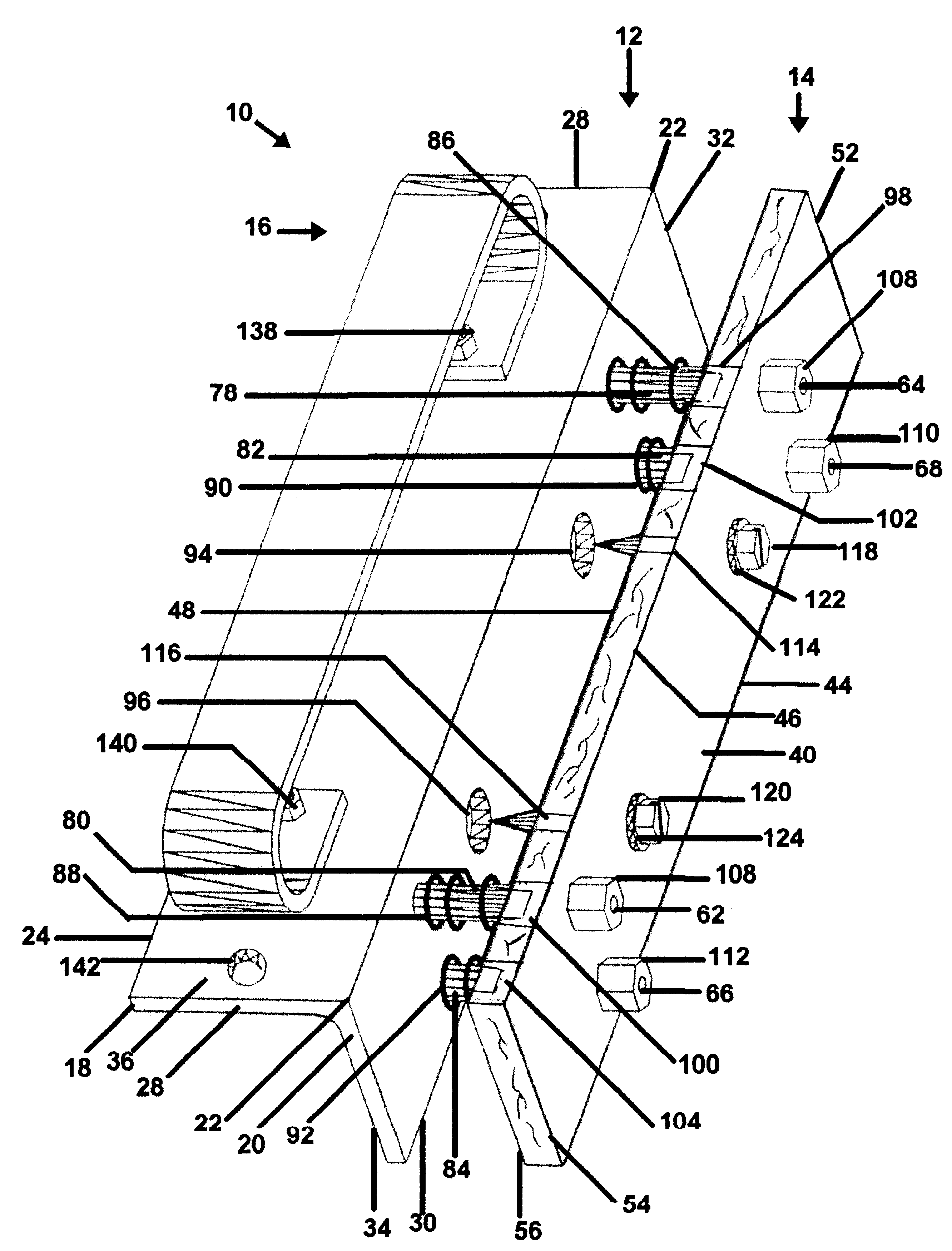
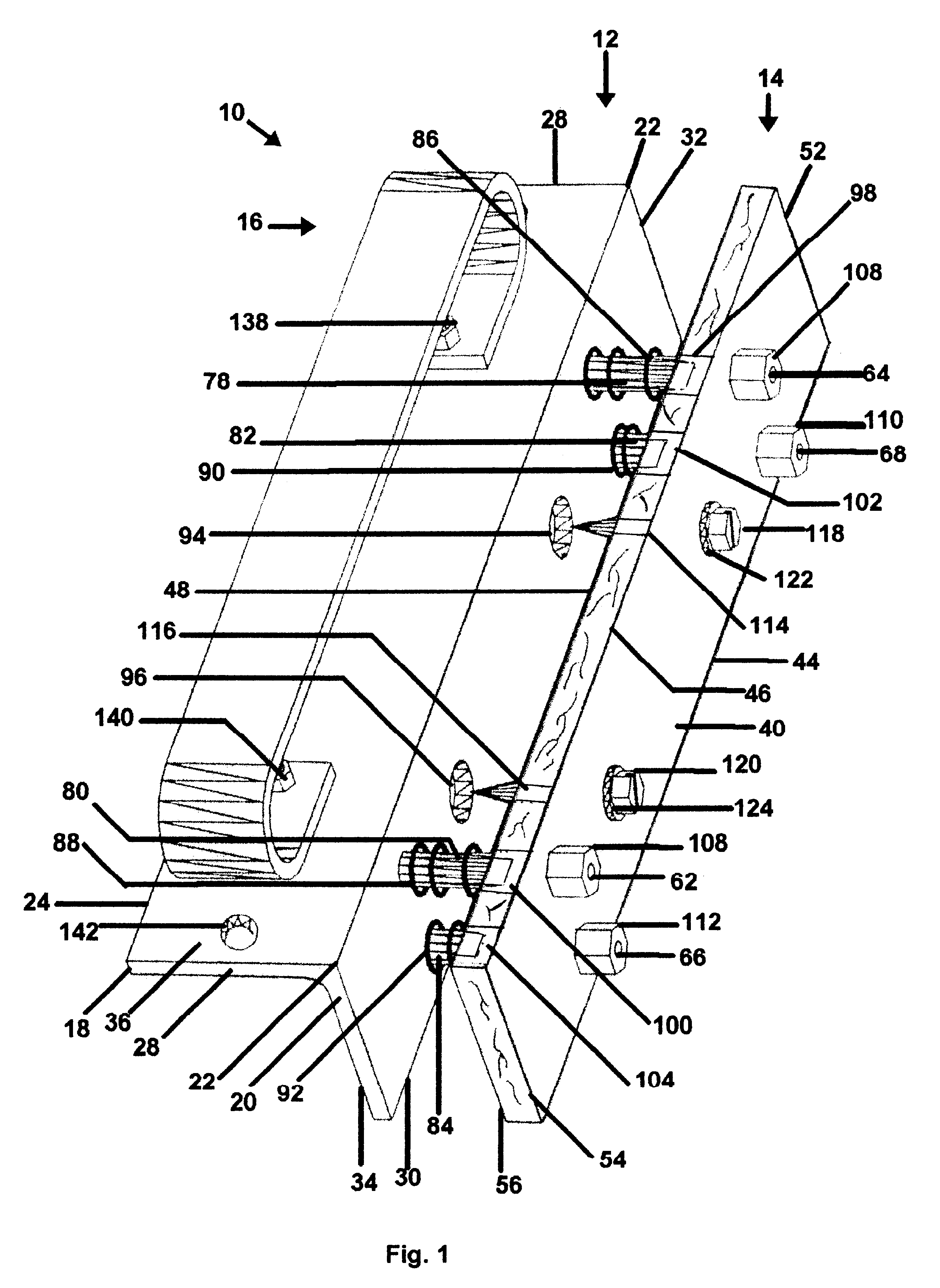
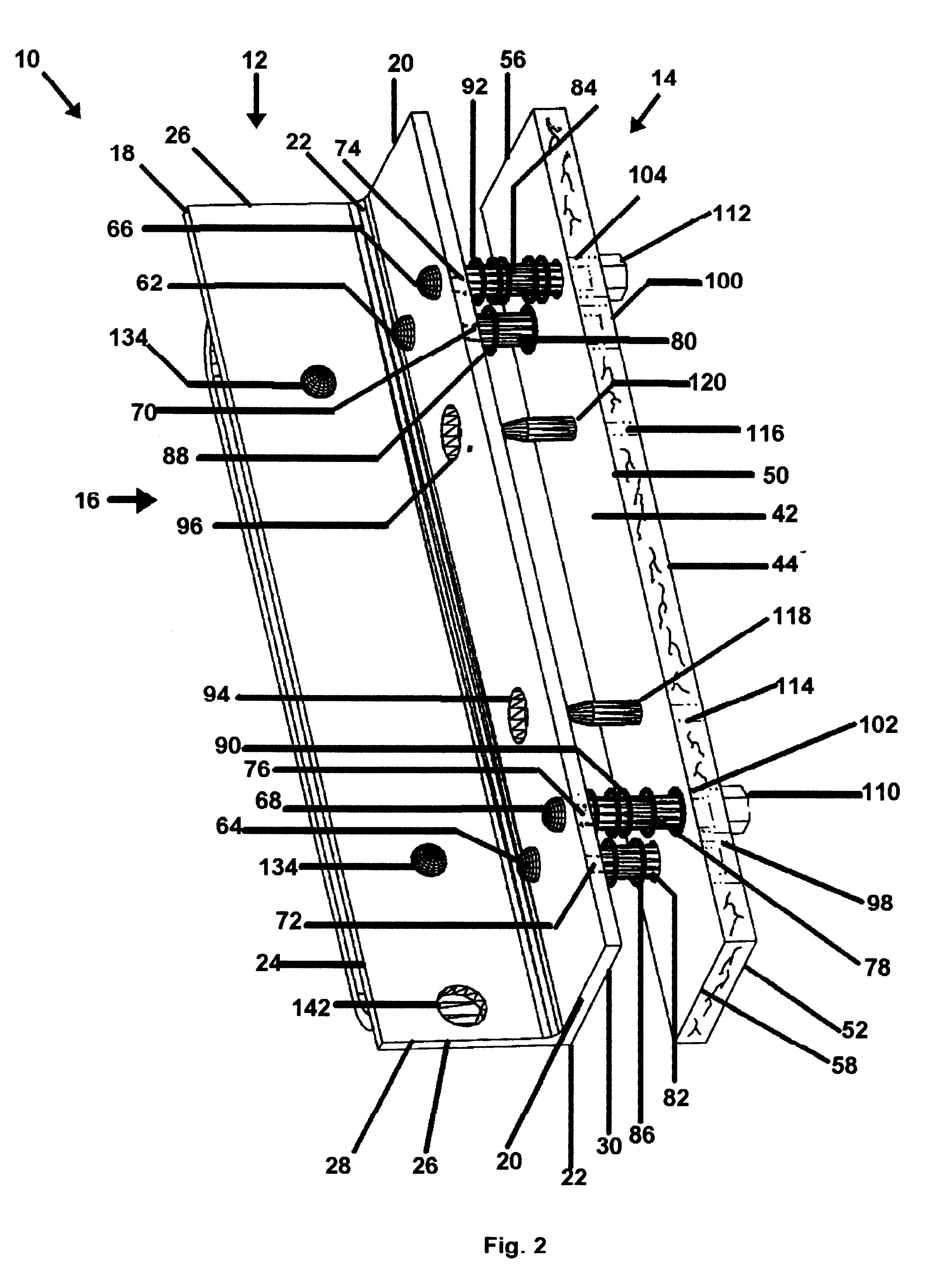
. 1-5

Referring now to the drawings, the present invention is generally referred to as number 10. A typical embodiment of the present invention is illustrated in FIG. 1, an isometric exterior view, FIG. 2, an isometric interior view and in FIGS. 3 and 4 illustrating an end view in detail. With references to FIGS. 1 through 4 the present invention is shown as comprising three assemblies: main body assembly 12, pressure plate assembly 14, and support handle assembly 16. With respect to the preferred embodiment, main body assembly 12 is a single piece of metal having a rigid right angle form the entire length. Main body assembly 12 is typically 7.500 in. (190.5 mm) long and with a thickness throughout of approximately 0.125 in.(3.175 mm). Main body assembly 12, being a right angle, has horizontal leg 18, vertical leg 20 and heel 22. Each leg extends the entire length of main body assembly 12 with a width typically of 1.5 in. (38.100 mm). Horizontal leg 18 has longitudinal edge 24 with h...


PUM


Abstract

An improved temporary hand held grip for engaging the edge of a cardboard, Styrofoam or wooden box that includes a right angle body to mate with the edge of a box and a plurality of teeth that penetrate a box contiguous to the edge of a box and just off side the edge. Each improved grip includes an attached leather strap connected to one angle side of the right angle body to aid in handling a box. The improvedgrip contains sufficient space to allow the fingers to grip the entire invention so as to prevent losing control of it when using it. The plurality of teeth are easily adjustable if it becomes necessary to adjust the depth of their penetration into the surface of the box being handled so as not to damage the contents of the box being handled while retaining a firm grip on the box. The improved grip also provides a means of preventing injuries from the sharp teeth by retracting when pressure is released when not being used tohandle a box.

Description

BACKGROUND--FIELD OF INVENTIONThe present invention relates generally to the use of a singular portable detachable grip which provides a temporary detachable grip and handle to engage the edge of a cardboard, Styrofoam or wood box for the purpose of handling said boxes.BACKGROUND--DESCRIPTION OF PRIOR ARTThe majority of boxes or cartons supplied industry today are of cardboard. A few are of Styrofoam and of wood. Except for wood their surfaces are smooth and slick. Such surfaces make them difficult to grasp for handling, especially if relatively heavy and large enough so that they are cumbersome to lift, pick up off the floor or otherwise difficult to handle. Boxes come in a multitude of sizes. Larger ones are sometimes cumbersome for one person to handle them for moving them. Some have built in handles but these will break while others have slots in their sides which work fine till they get wet and then they fail. Boxes are not always in a convenient location to allow them to be ea...

Claims


Application Information

Patent Timeline
Patent Type & Authority Patents(United States)
IPC IPC(8): B65G7/12B65G7/00
CPCB65G7/12
Inventor JORDENING, HAROLD GENE
Owner JORDENING HAROLD GENE
Why Eureka
Try Eureka