

Apparatus and a method for controlling an automatic transmission
a technology of automatic transmission and transmission mechanism, which is applied in the direction of gearing control, gearing elements, gearing generation, etc., can solve the problems of large torque drag, affecting the performance of the transmission, and generating drive torque drag
- Summary
- Abstract
- Description
- Claims
- Application Information
AI Technical Summary
Problems solved by technology
Method used
Image

Examples
Embodiment Construction
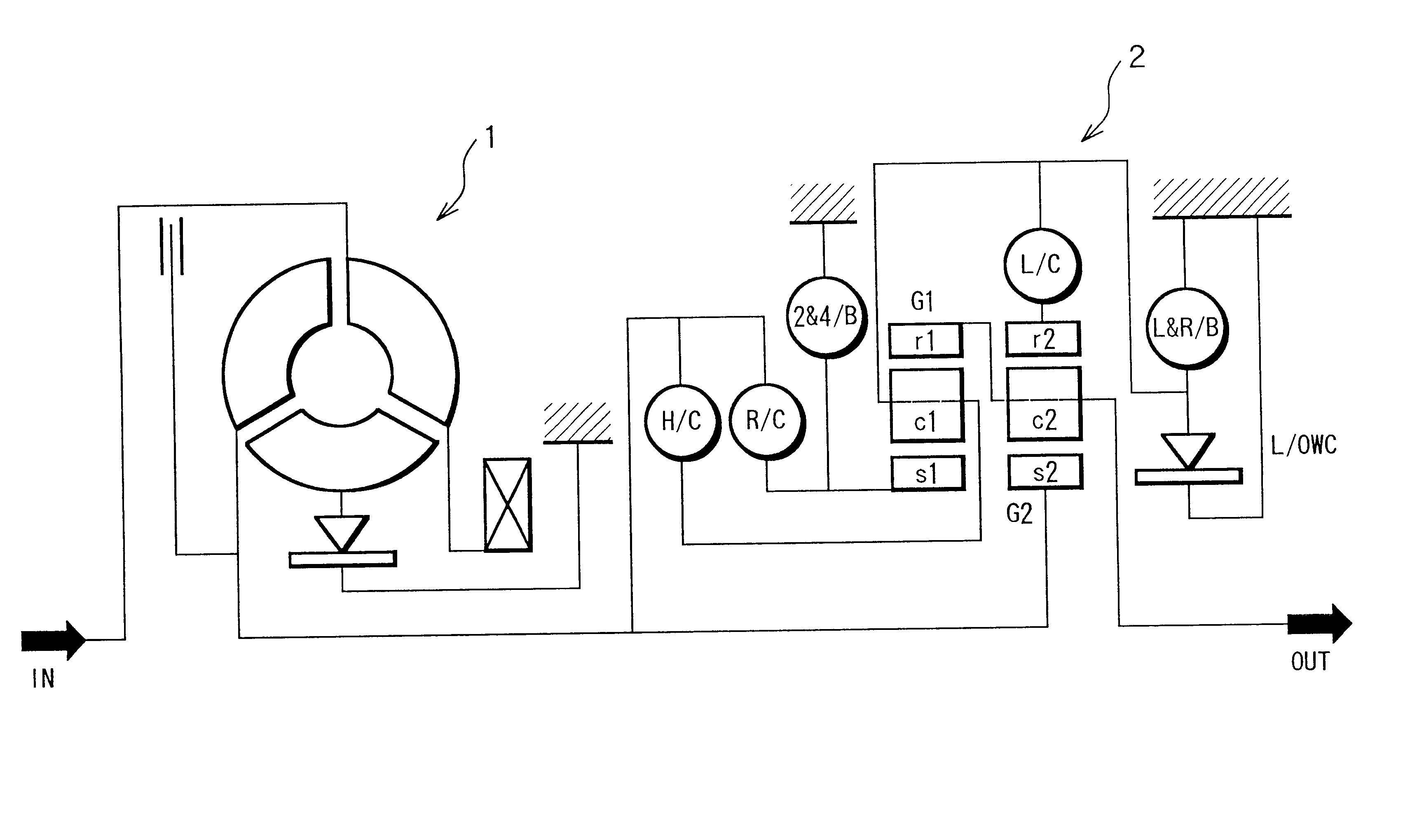
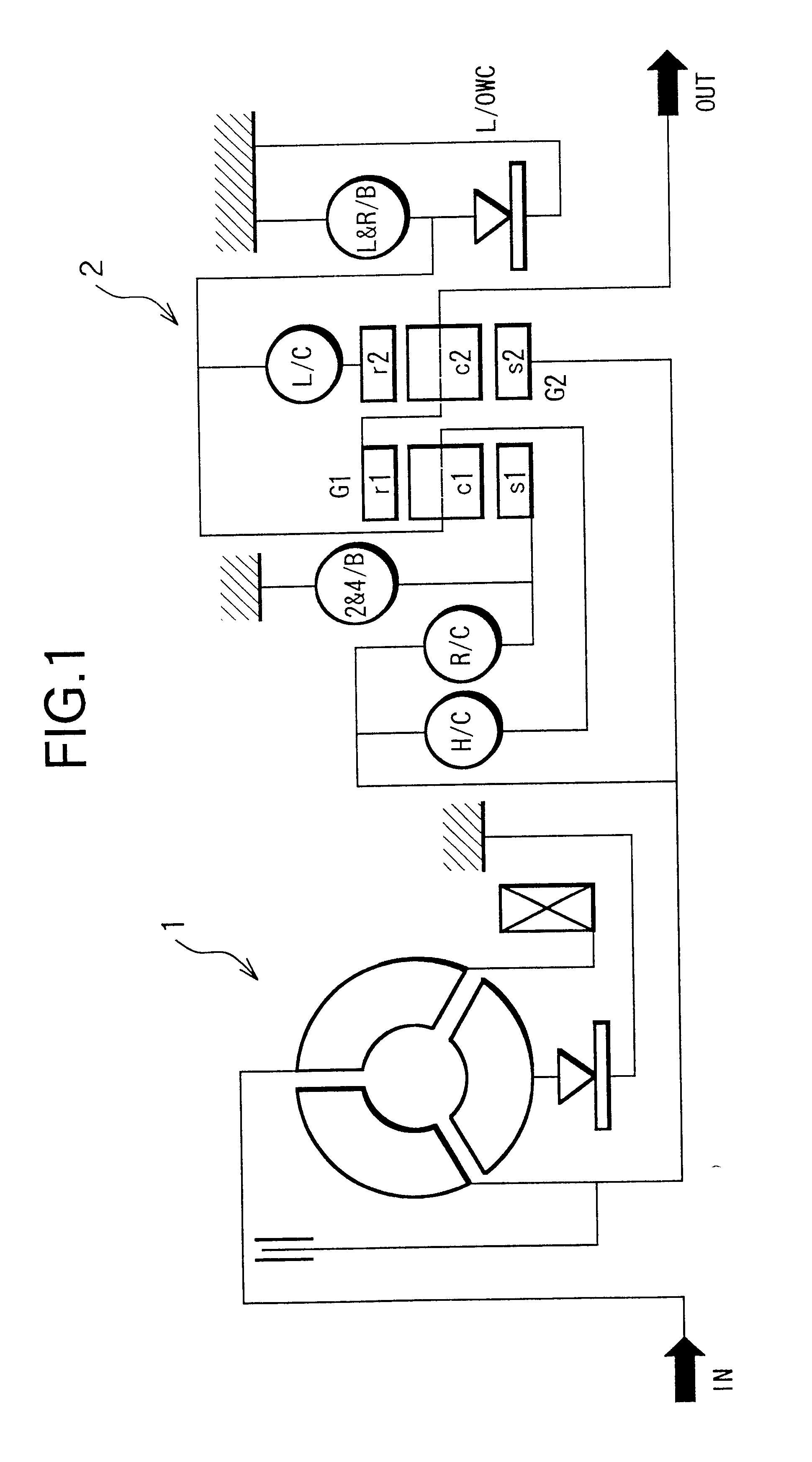
FIG. 1 shows a speed change mechanism of an automatic transmission in one embodiment, wherein an engine output is transmitted via a torque converter 1 to a speed change mechanism 2.
The speed change mechanism 2 includes two sets of planetary gears G1, G2, three sets of multi plate clutches H / C, R / C, L / C, a set of brake bands 2 & 4 / B, a set of multi plate brakes L & R / B and a set of one way clutches L / OWC.
Each of the two sets of planetary gears G1, G is a simple planetary gear having sun gears S1, S2, ring gears r1, r2, and carriers c1, c2.
The sun gear S2 of the planetary gear set G1 is constituted to be connectable to an input shaft IN by the reverse clutch R / C and to be fixed by the brake band 2 & 4 / B.
The sun gear S2 of the planetary gear set G2 is connected to the input shaft IN directly.
The carrier c1 of the planetary gear set G1 is constituted to be connectable to the input shaft IN by the high clutch H / C, the ring gear r2 of the planetary gear set G2 is constituted to be connect...
PUM
 Abstract
Description
Claims
Application Information