Multi-array LED warning lights

a warning light and led technology, applied in the direction of lighting and heating equipment, instruments, lighting support devices, etc., can solve the problems of inefficient use of light generated by closely spaced arrays of such devices, and impose relatively harsh operating conditions on light sources

Inactive Publication Date: 2002-08-13
WHELEN ENGINEERING COMPANY
View PDF4 Cites 150 Cited by
  • Summary
  • Abstract
  • Description
  • Claims
  • Application Information

AI Technical Summary

Problems solved by technology

However, LED's have characteristics which result in the light generated by a closely spaced array of such devices being inefficiently utilized.
The en

Method used


Image

  • Multi-array LED warning lights
  • Multi-array LED warning lights
  • Multi-array LED warning lights

Examples


Embodiment Construction

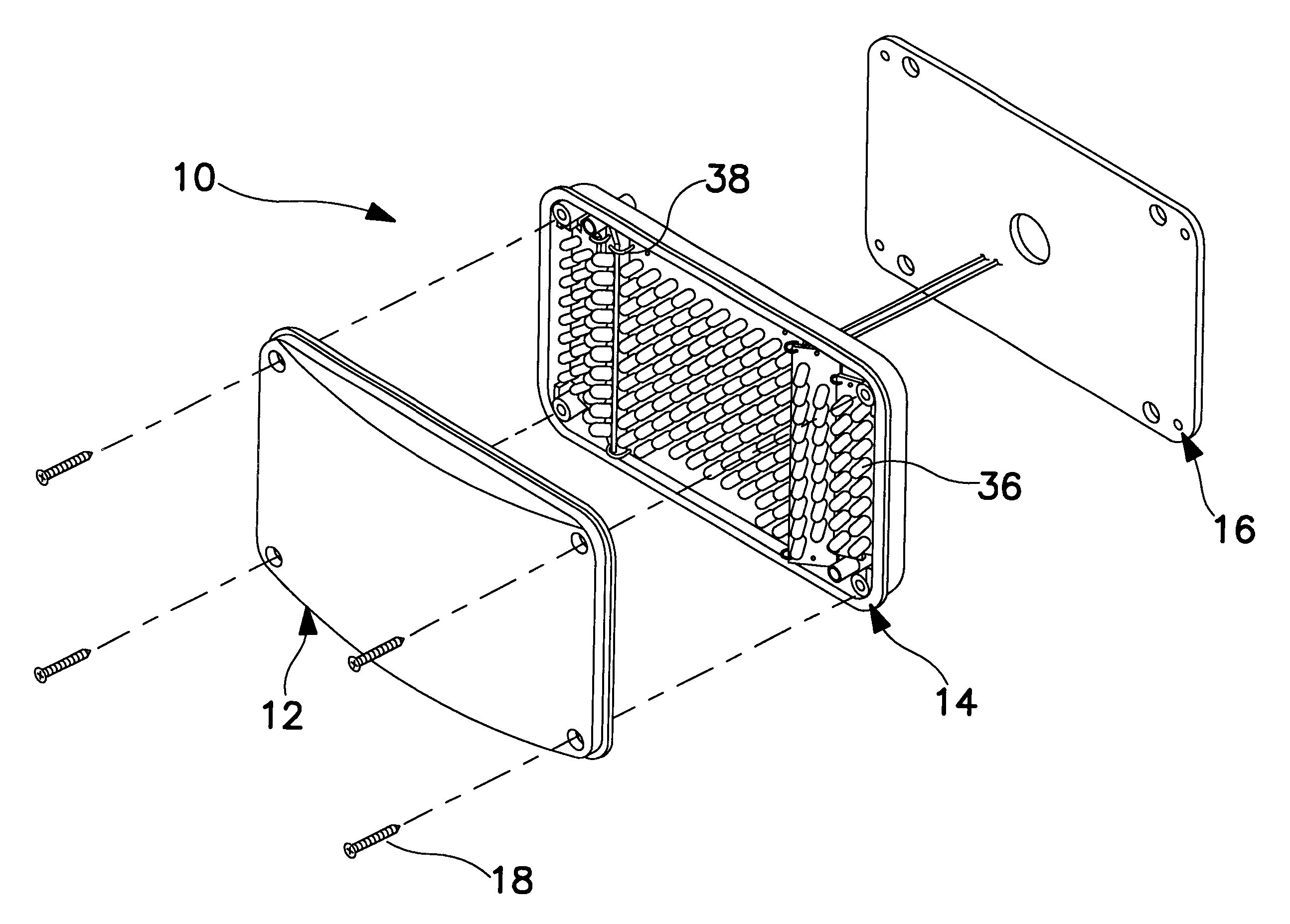
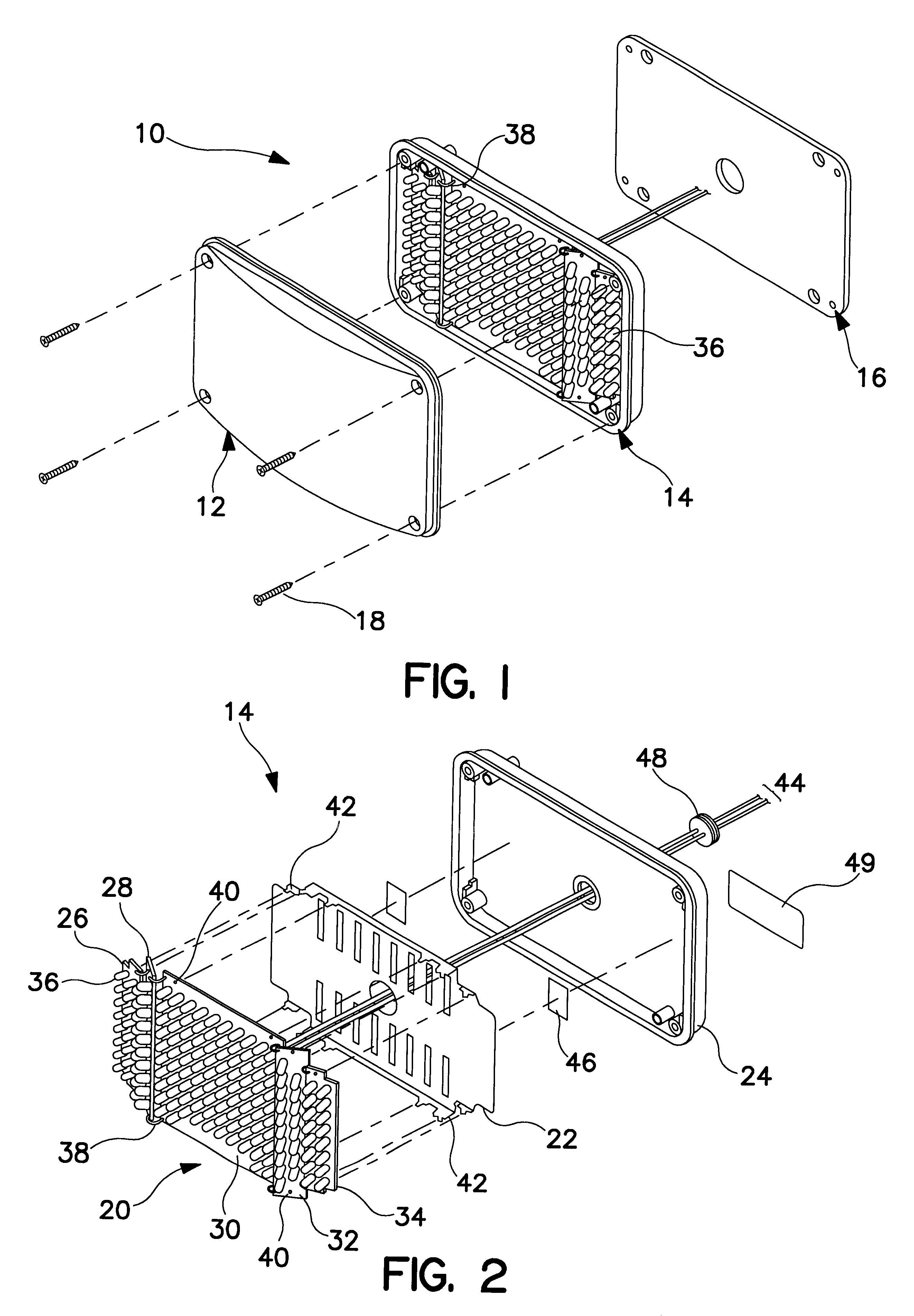
A warning light in accordance with a first embodiment of the invention is indicated generally at 10 in FIG. 1. Warning light 10 comprises three principle components, namely a "dust cover" 12, a light source 14, and a gasket 16. When the warning light, which is also referred to in the trade as a lighthead, is mounted on an emergency vehicle, for example through employment of the four mounting screws 18, gasket 16 will be compressed between the back of light source 14 and the exterior of the vehicle thus establishing a hermetic seal. Dust cover 12 engages light source 14 in such a manner as to establish a seal against the migration of dirt and moisture into the space between the dust cover and light source. Dust cover 12 thus further protects light source 14 from the ambient environment and, in so doing, provides a smooth surface which may be easily cleaned. Dust cover 12 preferably does not include optics but may, if necessary for the particular use, be tinted to impart a desired col...


PUM


Abstract

A warning light has multiple juxtapositioned arrays of light emitting diodes, each of the arrays defining a plane oriented transversely to the parallel axes of the lenses of the diodes comprising the array. The arrays are supported so that the planes defined thereby angularly intersect. The radiation pattern of the light is controlled by selection of the diodes comprising each array and adjustment of the angles of intersection of the array defined planes.

Description

1. Field of the InventionThe present invention relates to the generation of focused, high intensity light and, particularly, to warning lights comprised of multiple, closely spaced arrays of light emitting diodes. This invention is also directed to techniques for the fabrication of directional light sources, which produce highly visible radiation and, especially, to warning lights having plural arrays of light emitting diodes which define angularly intersecting planes. Accordingly, the general objects of the present invention are to provide novel and improved methods and apparatus of such character.2. Description of the Prior ArtRecent improvements in light emitting diodes (LED's), particularly the ability of such solid state devices to generate relatively high light flux, has permitted use of LED's in warning lights. Restated, presently available LED's, when grouped together to form a closely spaced array and energized simultaneously and periodically have the capability of producin...

Claims


Application Information

Patent Timeline
IPC IPC(8): B60Q1/26B64D47/00B64D47/06
CPCB60Q1/2696B64D47/06B64C2027/8236Y10S362/80B64D2203/00
Inventor FREDERICKS, THOMAS M.STOPA, JAMES L.
Owner WHELEN ENGINEERING COMPANY
Why Eureka
Try Eureka