
Supported golf bag

a golf bag and support technology, applied in the field of golf bags, can solve the problems of frequent failure of the operation mechanism of the legs to be deployed and withdrawn, excessive force, and frustrating and annoying for the golfer

Inactive Publication Date: 2002-08-20
KING POWER ENTERPRISE
View PDF12 Cites 34 Cited by
  • Summary
  • Abstract
  • Description
  • Claims
  • Application Information

AI Technical Summary

Problems solved by technology

The biggest problem with golf bags having retractable legs is that the operating mechanisms that deploy and retract the legs frequently do not function properly.
The golfer is often forced to repeatedly perform the manual actuating manipulation that is necessary to deploy or retract the legs, and to exert considerable force in doing so.
This is both frustrating and annoying to the golfer.
Moreover, because golfers must devote an inordinate amount of attention to ensuring that the retractable legs of their golf bag are properly deploy and returned, their concentration is impaired and their attention is distracted from performing the proper actions in executing their golf strokes.
While this system is advantageous in theory, as a practical matter it presents problems.
Specifically, a very considerable amount of force is required to actuate the mechanism that pushes the legs out away from the bag due to the poor leverage that exists in the actuating mechanism.
Also, frequently the driving plate does not rotate freely relative to the base at the bottom of the body of the bag, thereby resulting in binding of the hinge mechanism.
A further disadvantage of the system disclosed in this patent is that the bag is not stable when positioned in a vertically upright orientation.
To the contrary, it easily tips over when in this position.

Method used


Image

  • Supported golf bag
  • Supported golf bag
  • Supported golf bag

Examples


Embodiment Construction

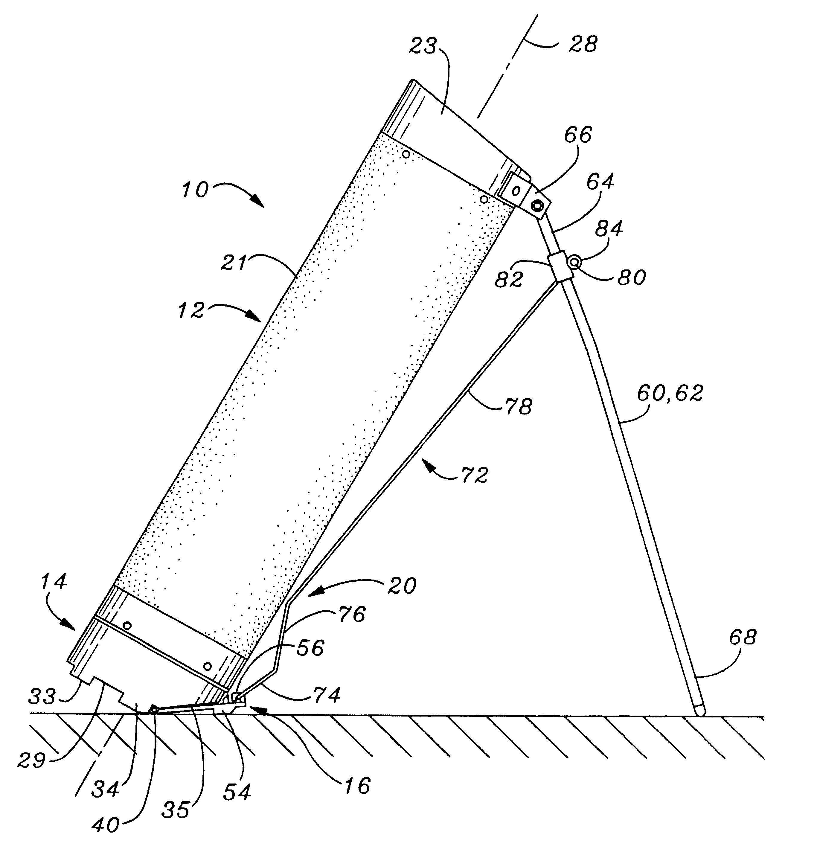
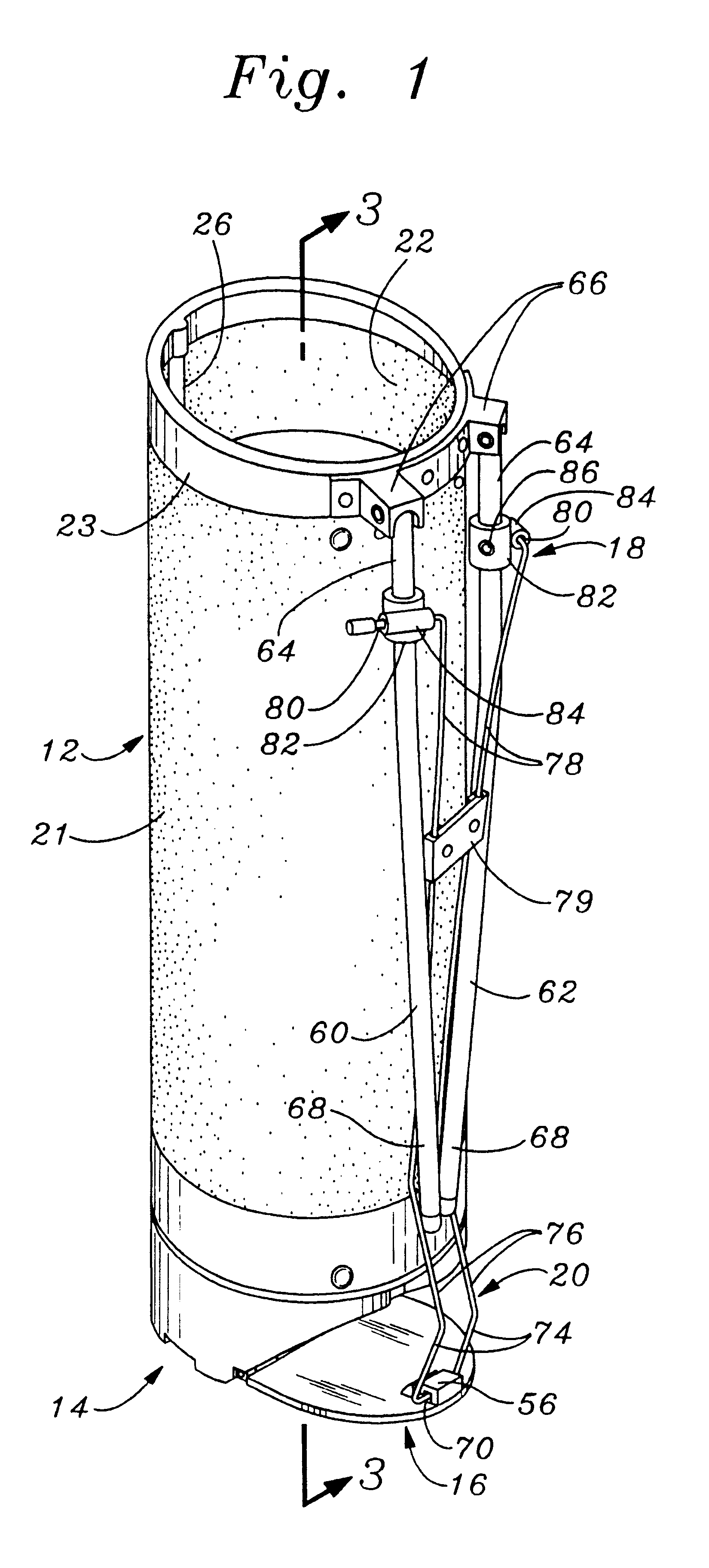
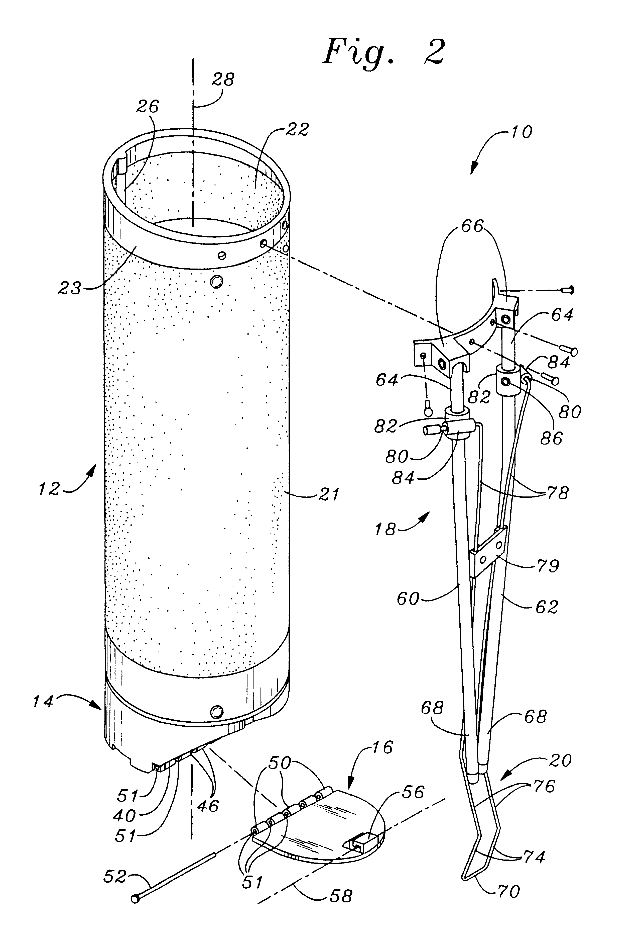
FIG. 1 illustrates a golf bag 10 constructed according to the invention. The golf bag 10 is comprised of a hollow tubular body 12 designed for storage of golf equipment, mainly golf clubs. In addition to the tubular body 12, the principal components of the golf bag 10 include a stiff base member 14 located at the closed end of the body 12, an actuation plate 16, a stand 18, and a spring wire leg spreader rod 20.

The hollow, tubular body 12 is formed of an elongated fabric wall structure 21 that surrounds and encloses an elongated cavity. At the upper end of the wall structure 21 the tubular body 12 has a stiff, plastic encircling collar 23 that delineates an open mouth to the cavity defined within the wall structure 21. The lower end of the tubular body 12 is closed by the base member 14, which is a stiff, plastic, cup-shaped lower end piece.

As in conventional golf bags, an elongated stiffening rod 26 has opposing ends that fit into sockets formed in the collar 23 and the stiff, bott...


PUM


Abstract

A golf bag is provided with a pair of legs hinged at a rigid collar at the upper extremity of the bag. The lower end of the bag is closed by a base member that defines a flat, planar sole perpendicular to the longitudinal orientation of the bag, and also an upwardly inclined heel. An actuation plate is attached by a leaf hinge connection to the base member at the transition between the sole and heel. Knuckles on the base member and actuation plate are interleaved with each other across the width of the base member. The actuation plate protrudes outwardly beyond the body portion of the bag a distance of at least one inch. A spring wire spreader rod has a central, bight portion that is captured by a spreader hinge bracket located at the upper, outboard edge of the actuation plate. The wire spreader rod is configured with segments oriented at obtuse and reflex angles to provide improved leverage in deploying the legs. The interleaved knuckle hinge connection prevents the actuation plate from binding relative to the base member. The outward protrusion of the actuation plate reduces the torque required to deploy the legs and also provides greater stability for supporting the bag in an upright disposition.

Description

1. Field of the InventionThe present invention relates to a golf bag designed to be carried by a golfer and which is self-supporting in both an upright, vertical orientation and in an inclined orientation.2. Description of the Prior ArtGolf bags having retractable legs to allow the bag to be supported in an inclined orientation have been available for many years. The purpose of providing a golf bag with retractable supporting legs is to allow the bag to the supported in a stable orientation in which the tubular body of the bag resides at an incline relative to the surface upon which the bag is placed. The deployed legs, together with the tubular body of the bag, provide a very stable, tripod type of support in which the clubs are easily visible to the golfer and in which they can be easily pulled from and returned to the tubular body.The biggest problem with golf bags having retractable legs is that the operating mechanisms that deploy and retract the legs frequently do not function...

Claims


Application Information

Patent Timeline
IPC IPC(8): A63B55/00A63B55/04A63B55/57
CPCA63B55/04A63B55/57A63B55/50
Inventor WANG, CHING LING
Owner KING POWER ENTERPRISE
Learn More