Nasal cannula

a cannula and a technology of cannulas, applied in the direction of valves, respirators, mechanical equipment, etc., can solve the problems of increasing the risk of gas mixing, vexing problems, and affecting the reading of end-tidal carbon dioxide, so as to reduce or eliminate the incidence of occlusion

Inactive Publication Date: 2002-08-27
SALTER LABS
View PDF5 Cites 349 Cited by
  • Summary
  • Abstract
  • Description
  • Claims
  • Application Information

AI Technical Summary

Benefits of technology

It is therefore an object of the present invention to provide a nasal cannula structure for sampling carbon dioxide which reduces or eliminates the incidence of occlusion of the tip of the carbon dioxide sampling nare during the removal of carbon dioxide by the sampling line connected to a monitoring device and / or a source of suction or vacuum.
It is also an object of the present invention to provide a nasal cannula for insufflating a patient with oxygen while accurately monitoring end-tidal carbon dioxide, that will continue to function properly for its intended purpose when either or both nares become occluded for any reason.
It is a further object to accomplish the foregoing objects with a minimum risk of distorting the end-tidal carbon dioxide readings from the sampled exhalation gases during the administration of anesthesia.

Problems solved by technology

The cannula is preferably provided with an internal wall or system in the face piece to keep the conduits separate for insufflation and sampling, however, separate lines can be used or even multiple nares for insufflation and sampling, though the latter device substantially increases the risk of gases mixing which can distort the readings for end-tidal carbon dioxide.
Conversely, problems can be encountered if the patient is horizontal or prone and tends to accumulate secretions in the nasal cavities.
It can be a particularly vexing problem if either the insufflation or sampling nare becomes occluded during the use of the cannula for sampling and monitoring end-tidal carbon dioxide during the administration of anesthesia.

Method used


Image

  • Nasal cannula
  • Nasal cannula

Examples


Embodiment Construction

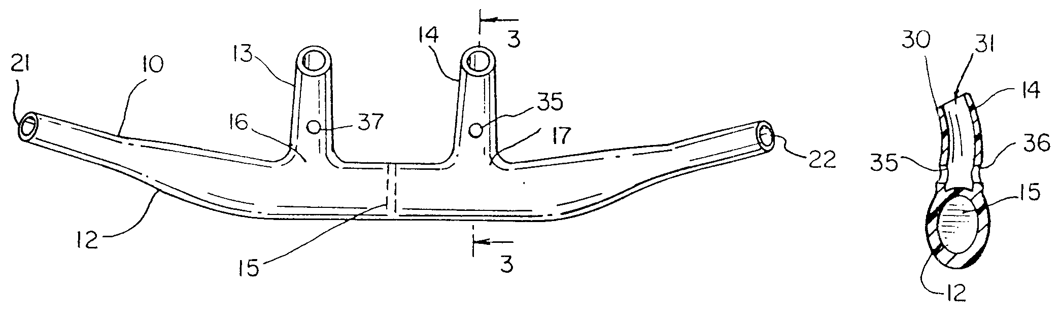
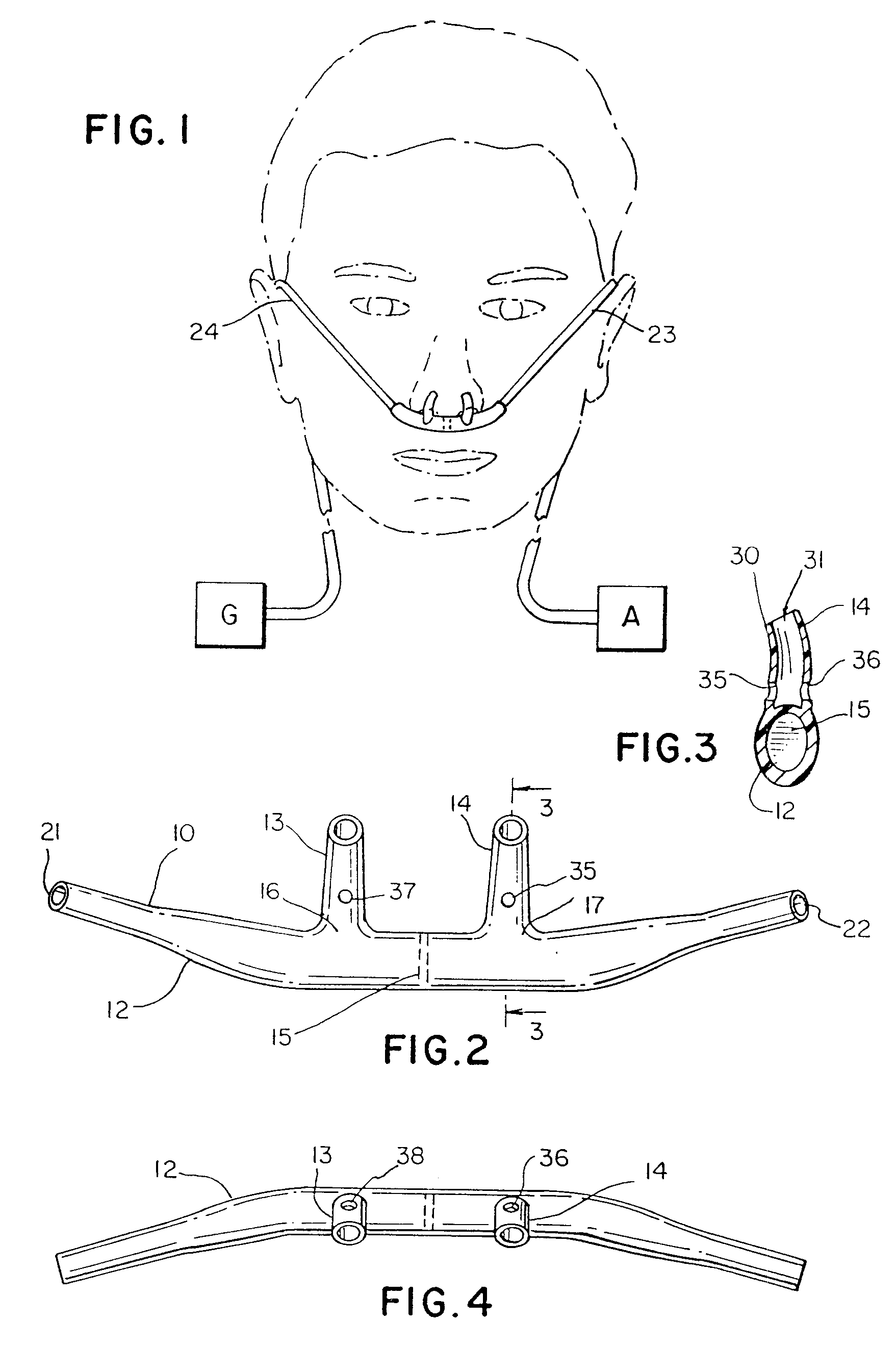
The nasal cannula 10 of one embodiment of the present invention consists of a generally tubular face piece 12 having two nares 13 and 14 and a septum 15 disposed in the center of the face piece 12 between the openings 16 and 17, respectively, of the nares 13 and 14 (see FIGS. 2, 3 and 4). The openings 21 and 22 on the ends of the face piece 12 are affixed to separate tubes 23 and 24 as shown in FIG. 1, which are separately connected to a source of insufflating gas (G), such as oxygen, and a commercial carbon dioxide monitoring unit (shown as A) which, in turn, has or is connected to a vacuum pump or other means for drawing exhaled breath containing carbon dioxide into an instrument that is capable of measuring the concentration of the carbon dioxide in the sampled gas.

During use of the cannula for both insufflation and the monitoring of carbon dioxide concentration in the exhaled breath (depicted schematically in FIG. 1), the readings for end-tidal carbon dioxide can become distorte...


PUM


Abstract

An apparatus for insufflating a treating gas into a patient and for measuring a carbon dioxide content exhaled by the patient includes a hollow body with a partitioning wall separating the body into inhalation and exhalation manifolds. Two hollow prongs have coaxial openings close to the body which allow gas exchange for breathing and carbon dioxide measuring purposes. The holes are of a size such that suction drawn through the holes is limited while still allowing accurate gas analysis.

Description

The practice of measuring end-tidal carbon dioxide during the administration of anesthesia, particularly regional anesthesia, has grown markedly in the past several years. The reasons that anesthesiologists have embraced this technique are described more fully in U.S. Pat. No. 5,335,656 which is incorporated herein by reference in its entirety.The preferred nasal cannula used in this procedure is a cannula which insufflates the patient with oxygen through one nare of a cannula and separately samples the exhaled gases by drawing the exhaled gas from the other nare into a conventional carbon dioxide analyzer. The cannula is preferably provided with an internal wall or system in the face piece to keep the conduits separate for insufflation and sampling, however, separate lines can be used or even multiple nares for insufflation and sampling, though the latter device substantially increases the risk of gases mixing which can distort the readings for end-tidal carbon dioxide. It is prefe...

Claims


Application Information

Patent Timeline
Patent Type & Authority Patents(United States)
IPC IPC(8): A61M16/06
CPCA61M16/0666A61M2210/0625A61M2230/432Y10S128/912A61M16/085
Inventor CURTI, JAMES N.CHUA, JAMESSALTER, PETER W.
Owner SALTER LABS
Why Eureka
Try Eureka