
Nasal cannula for acquiring breathing information

a technology of breathing information and cannula, which is applied in the field of cannula, can solve the problems of affecting the reading of end-tidal carbon dioxide, affecting the operation of the valve, so as to reduce or eliminate the incidence of occlusion of the tip

Inactive Publication Date: 2010-01-05
SALTER LABS
View PDF20 Cites 19 Cited by
  • Summary
  • Abstract
  • Description
  • Claims
  • Application Information

AI Technical Summary

Benefits of technology

The secondary openings prevent occlusion of the primary inlet / outlet, maintaining proper nasal cannula function and reducing the risk of distorted CO2 readings, allowing continuous monitoring of breathing characteristics and end-tidal CO2 during anesthesia, even when the primary path is obstructed.

Problems solved by technology

The cannula is preferably provided with an internal wall, a partition, a barrier or a system in the face piece to keep the conduits completely separate from one another for insufflation and sampling, however, separate lines can be used or even multiple nares for insufflation and sampling, though the latter device substantially increases the risk of gases mixing which can distort the readings for end-tidal carbon dioxide.
Conversely, problems can be encountered if the patient is horizontal or prone and tends to accumulate secretions in the nasal cavities.
It can be a particularly vexing problem if either the insufflation or sampling nare becomes occluded during the use of the cannula for sampling, monitoring end-tidal carbon dioxide during the administration of anesthesia, detecting pressure or breathing characteristics of a patient, etc.
One problem which can readily occur during use of a cannular positioned in the nostrils of a patient is that the primary opening, formed in the remote end wall or surface, of one or both of the nares may become either partially or fully occluded, blocked, clogged or otherwise obstructed by, for example, mucosal secretions and / or soft mucosal tissue during use of the nasal cannula.

Method used


Image

  • Nasal cannula for acquiring breathing information
  • Nasal cannula for acquiring breathing information
  • Nasal cannula for acquiring breathing information

Examples


Embodiment Construction

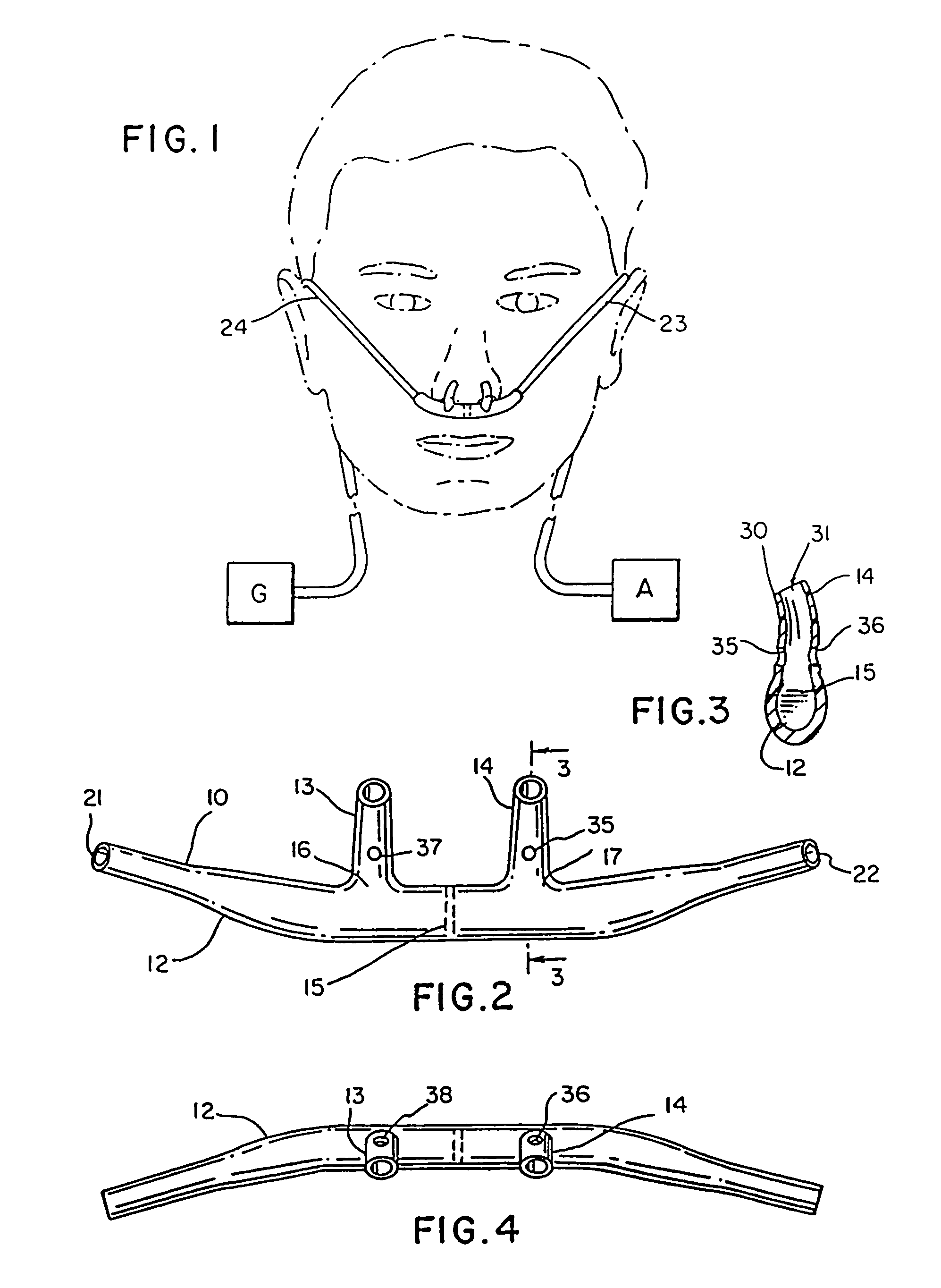
[0017]FIG. 1 is a frontal view of a normally positioned nasal cannula on a patient (shown in phantom) connected to a gas source (G) and a gas analyzer (A);

[0018]FIG. 2 is a rear view of the cannulae face piece shown in FIG. 1;

[0019]FIG. 3 is a partial cross section of a nare of the nasal cannula taken along the lines and arrows 3-3 of FIG. 2;

[0020]FIG. 4 is a top plan view of the nasal cannula of FIG. 2;

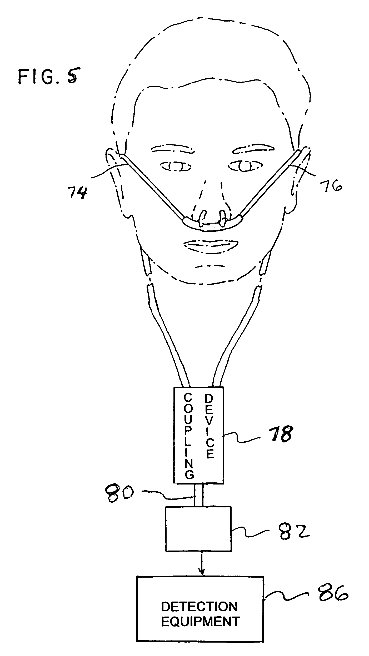
[0021]FIG. 5 is a diagrammatic view of a nasal cannula for connection to detection equipment to facilitate monitoring of breathing characteristics of a patient;

[0022]FIG. 6 is a diagrammatic view of a nasal cannula, with a mouthpiece, for connection to detection equipment to facilitate monitoring of breathing characteristics of a patient;

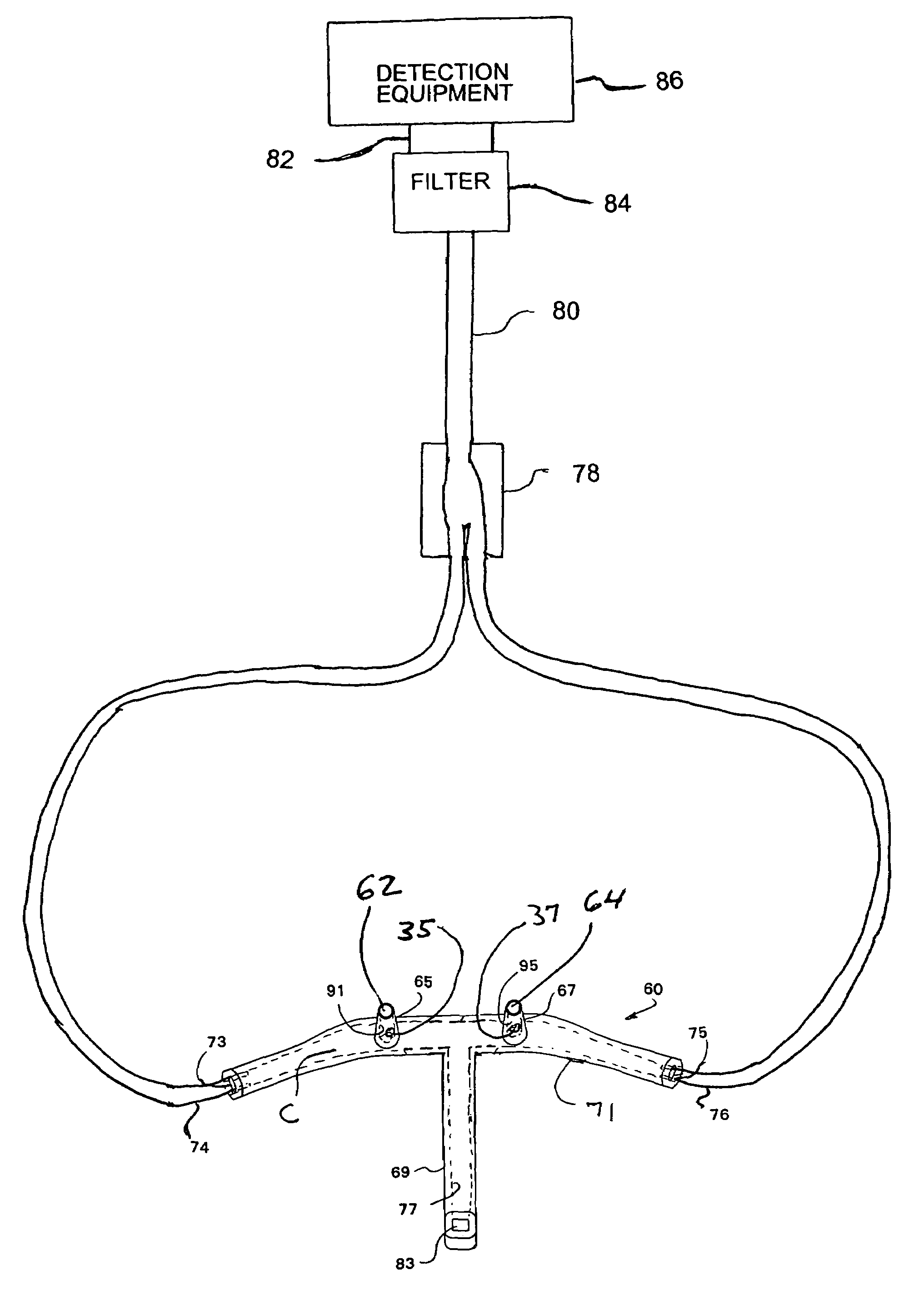
[0023]FIG. 7 is a diagrammatic view of a nasal cannula, with a mouthpiece but without any secondary openings in the nares, for connection to detection equipment to facilitate monitoring of breathing characteristics of a patient;

[0024]FIG. 8 is a diag...


PUM


Abstract

A method of monitoring breathing of a patient with a nasal cannula. The method comprising the steps of forming the nasal cannula with at least one nare, and at least one nare having a primary inlet / outlet opening formed in a remote end thereof. Coupling the nasal cannula to a detection device for monitoring breathing characteristics of the patient while the patient is sleeping. Detecting breathing characteristics of the patient, while the patient is sleeping, via at least the primary inlet / outlet opening of the nare and sending the detected breathing characteristics of the patient to detection device for evaluation.

Description

[0001]This application is a continuation-in-part of patent application Ser. No. 10 / 627,502 filed Jul. 25, 2003 now abandoned which is a divisional of patent application Ser. No. 09 / 837,720 filed Apr. 18, 2001 now U.S. Pat. No. 6,655,385 which is a continuation of patent application Ser. No. 09 / 184,111 filed Nov. 2, 1998 now U.S. Pat. No. 6,439,234 which is a continuation of International Application PCT / US98 / 05573 filed Apr. 3, 1998 which claims the benefit of provisional patent application Ser. No. 60 / 045,080 filed Apr. 29, 1997.FIELD OF THE INVENTION[0002]The present invention relates to a cannula which is provided with a pair of nares which each have a primary aperture or opening formed in an end surface or wall thereof defining a primary flow path into and out of the nare for supplying a desired gas to a nostril of a patient, withdrawing or sampling a desired gas from a nostril of a patient (e.g., sampling end tidal CO2 in the exhaled gases of a patient), monitoring breathing ch...

Claims


Application Information

Patent Timeline
Patent Type & Authority Patents(United States)
IPC IPC(8): A61M15/08A61M15/00A61M16/00A61M16/06
CPCA61B5/083A61B5/087A61B5/097A61B5/4806A61M16/085A61B5/6819A61M16/0666A61M2210/0625A61M2230/432A61B5/4818
Inventor CURTI, JAMES N.SALTER, PETER W.CHUA, JAMES
Owner SALTER LABS
Learn More