However, the greatest number of errors in key duplication occurs with the incorrect selection of the key blank since the differences in the aforementioned grooves and indentations are often too minute for correct manual identification.
A mistake in selection usually results in repeated duplication using yet another key blank, additional costs acquired due to the locksmith's time, and possible loss of business.
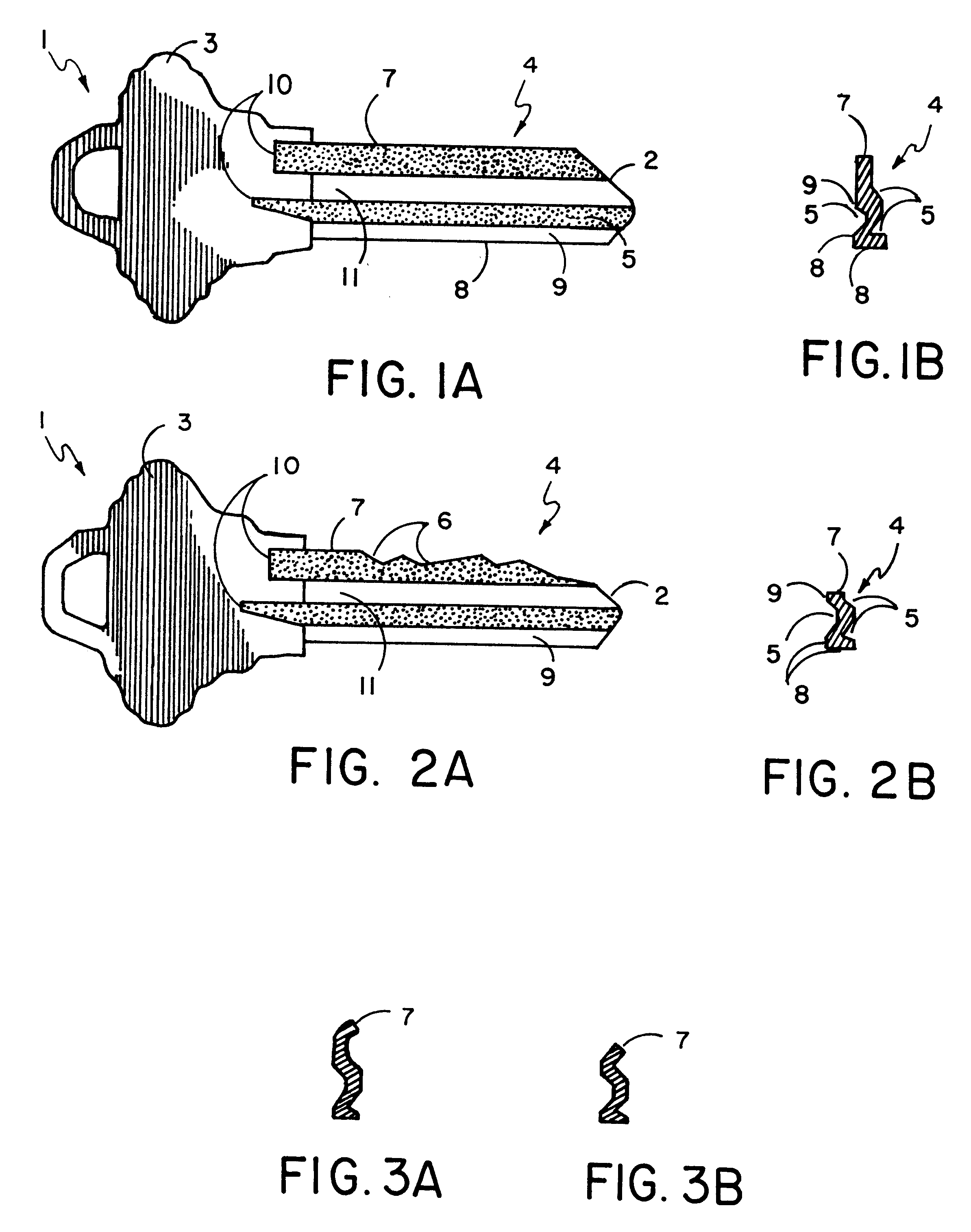
1. The actual height of the shank of the inserted key differs greatly from the heights of the shanks of the stored images. The variance in size can be 35% of a single side to 50% of double-sided keys. This is clearly shown in FIGS. 1A, 1B, 2A and 2B. FIG. 1A shows a side view of an uncut key blank. FIG. 1B shows the front cross-section of said key blank. FIG. 2A represents the same key which was notched (
cut) along top 7. FIG. 2B shows the front cross-section of the key displayed in FIG. 2A. When comparing FIG. 1B to FIG. 2B a difference in size can be clearly seen. This is of particular interest when compared to stored cross-sectional images of different key blanks shown in FIGS. 3A and 3B. These images may be selected by the automated
system as correct b
2. The key blanks are further differentiated by measuring grooves and indentations 5 along shank 4 (FIGS. 1B and 2B). As plainly seen in FIGS. 1B and 2B grooves and indentations 5 are rather small and complex geometric shapes which are difficult to visualize and compare due to a small surface area. Analysis of grooves and indentations 10 of FIGS. 1A and 2A based on the lateral scan of the key blank presents a larger surface area for examination and comparison;
3. Due to
wear and tear on the key, the geometric shape of its front cross-section changes, causing errors in identification;
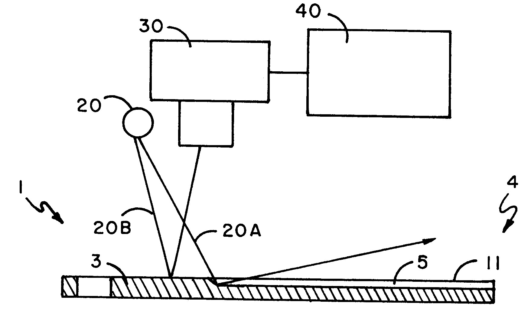
4. Correct projection of the front cross-section of a key depends greatly on the holding device which will hold the key in a desired position relative to the
light source. Any deviation from the desired position will cause
optical distortion and errors in identification;
5. Evaluation of the front cross-section of a key does not allow for measurement of the key's length;
6. Evaluation of the front cross-section of a key does not allow for detection of notches of top 7 which is necessary for actual duplication of the key; and
7. Evaluation of the front cross-section does not allow for the evaluation of the head of the key which often times serves as a differentiating factor during identification.
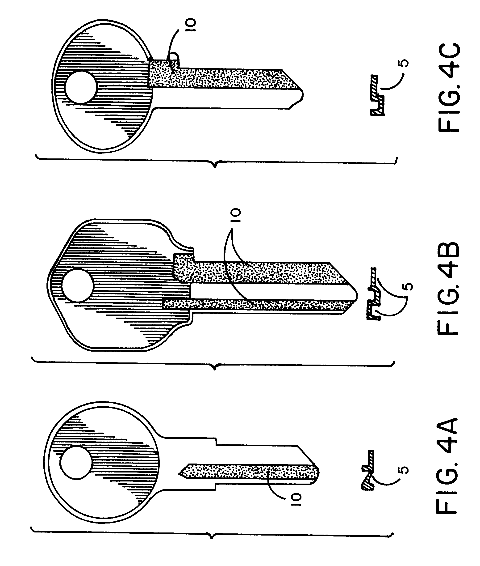
1. The apparatus and method according to this invention forms images of the grooves and indentations 5 on shank 4 of key 1 of FIG. 2A such that the image of the grooves and indentations 5 and 10 of a notched key and unnotched key is identical and unchanged in their geometrical structure even when key 1 is uniquely notched, as seen in notches 6 of FIG. 2A. This process dramatically increases the probability of a precise match.
2. Since indentations 5 on the shank 4 of key 1 do not actively participate in the operation of the lock and are spared the
wear and tear which distort the grooves and indentations at tip 2 of shank 4 on key 1, the images of the lateral surfaces according to this invention dramatically increases the probability of a precise match.
3. The shadow trace images of the lateral surface of shank 4 of key 1 has a much larger surface area than the surface area of the front cross-section of the front tip of key 1. The larger surface area is easier to scan and identify. Using FIG. 1A as an example, imaging the lateral surface images the grooves and indentations 5 in FIG. 1A throughout shank 4, and the shadow trace images may be calculated using the entire length of shank 4, whereas imaging the front cross-section only allows the measurement of space a-b of FIG. 1B which image is much smaller and harder to measure precisely.
4. The length of the key also serves as an identifying factor of the key. Often times keys may have identical cross-sections but different lengths of the shank, making the two keys' blanks different.
5. Scanning of the lateral surfaces of the key allows for measurement of the length of its shank as well as imaging the grooves and indentations 5 and 10. Therefore, scanning of the front cross-section does not allow lateral
surface scanning and scanning of the unique notches 6 of top 7 of key 1 which process excludes yet another factor which aids in key blank identification.
6. There is no need for a holding device which secures the key in a specific position as required for the evaluation of the front cross-section.
7. The head 3 of key 1 can also serve as an identifying feature. Other and further objects, as well as various advantages and features of novelty which characterize the invention, are pointed out with particularity in the claims annexed hereto and form a part hereof. However, for a better understanding of this invention, its advantages and objects obtained by its use, reference should be had to the drawings which form a further part hereof and to the accompanying descriptive matter, in which there is illustrated and described a preferred embodiment of the invention. Often times keys may have matching geometrical features on shank 4 but will vary greatly in the shape of head 3.

