Vehicle dispensing system

a technology for dispensing systems and vehicles, which is applied in the direction of applications, transportation items, roads, etc., can solve the problems of wasting construction materials, wasting construction materials, and wasting construction materials, and achieves the effects of reducing the visibility of the rear mounted dispensing apparatus with respect to the driver of the vehicle, and avoiding the use of wasteful and time-consuming two-step procedures

Inactive Publication Date: 2002-10-15
YAHOO INC
View PDF16 Cites 19 Cited by
  • Summary
  • Abstract
  • Description
  • Claims
  • Application Information

AI Technical Summary

Problems solved by technology

This two-step procedure is not only tedious and time consuming but also leads to waste of construction material.
While the above modification to existing dump trucks facilitates their conversion for dispensing granular material such as gravel or for sanding purposes in the wintertime, it will be appreciated that the visibility of the rear mounted spreading apparatus is limited with respect to the driver of the vehicle.
Indeed, there is no ability for the driver to inspect the material carried by the conveying system during spreading.
Also, frequently, the operator cannot see activities behind the truck because the body of the truck may block the view.
This creates a considerable potential for injury to people located nearby the truck.
Furthermore, regardless of the type of dispensing system used, rear dispensing trucks must be backed up to a worksite such that the front end of the truck may block traffic or otherwise interfere with the surrounding environment.
Another main drawback associated with prior art structures relates to the lack of versatility with regards to the configuration dispensing spray pattern.
This lack of versatility in the type of dispensing spray patterns often leads to the necessity for second step maneuvers such as requiring further processing of the dispensed material with rakes or other machinery.
The lack of versatility in the type of dispensing spray pattern also leads to a lack of versatility in the type of disp

Method used


Image

  • Vehicle dispensing system
  • Vehicle dispensing system
  • Vehicle dispensing system

Examples


Embodiment Construction

:

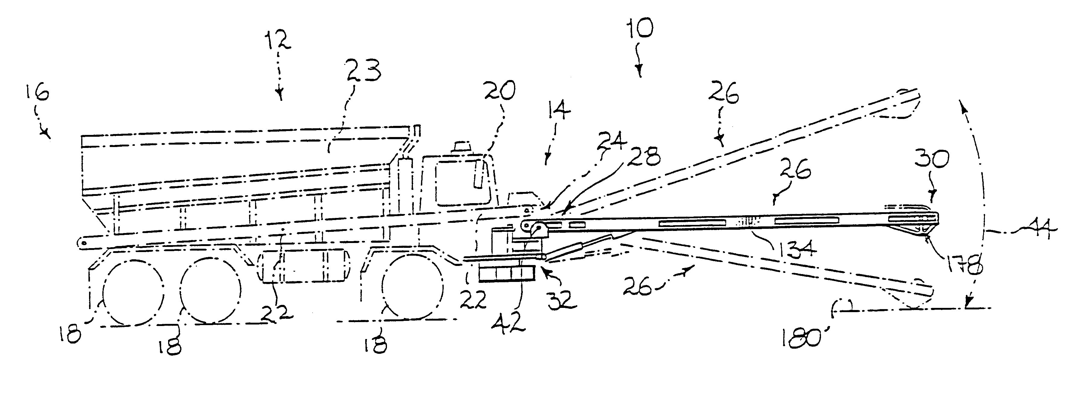
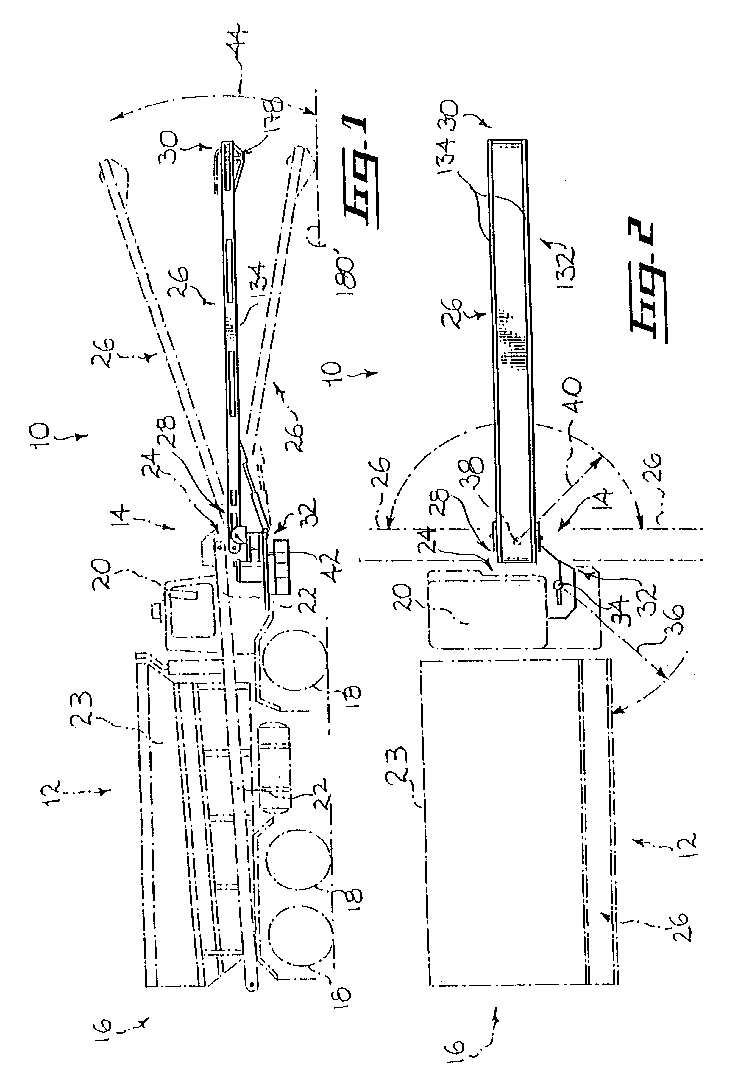
Referring to FIGS. 1 and 2, there is shown a material dispensing system 10 in accordance with an embodiment of the present invention. The material dispensing system 10 is shown attached to a conventional vehicle 12 such as a vehicle conventionally used for delivering flowable material. The flowable material may be of the granular type such as sand, gravel, small rocks or the like or any other suitable type such as semi-liquid or liquid material.

The vehicle 12 defines a vehicle front end 14 and a vehicle rear end 16. The vehicle 12 includes a vehicle frame mounted on wheels 18. An operator cab 20 is mounted on the vehicle frame adjacent the vehicle front end 14. A material container 23 such as a box like container, a hopper or the like is mounted on the vehicle frame rearwardly relative to the operator cab 20. The material container 23 is adapted to contain the flowable material and has a container bottom wall defining a container outlet aperture (not shown). A blocking gate (also n...


PUM


Abstract

A flowable material delivering vehicle in combination with a material dispensing system including a fixed conveyor extending continuously from a position located adjacent a vehicle container outlet aperture to a position located adjacent a vehicle cab front end. A dispensing adapter is attached to the vehicle for receiving a portion of the flowable material when the latter emanates from the fixed conveyor. In one embodiment, the dispensing adapter includes a pivotable conveyor pivotally attached to the vehicle and a configuring mechanism. The configuring mechanism allows the pivotable conveyor to pivot between a stowed configuration wherein it lies in a generally proximal and parallel relationship relative to an edge of the vehicle and a working configuration wherein the pivotable conveyor extends away from the vehicle so as to allow discharging of the flowable material away from the vehicle. In another embodiment, the dispensing adapter includes a dispensing chute defining a chute inlet end positioned adjacent the fixed conveyor discharge section, a laterally and downwardly extending chute body and a chute outlet end positioned laterally relative to the vehicle.

Description

FIELD OF THE INVENTION:The present invention relates to the field of dispensing systems and is particularly concerned with an adjustable dispensing system for mounting on the front end of transportation vehicles.BACKGROUND OF THE INVENTION:There exists a variety of situations wherein it is desirable to transport loose bulk material such as gravel, loose salt, rocks or the like to a specific site and dispense the material at a predetermined location according to a predetermined dispensing pattern. For example, gravel and compacted stones are often required for the construction of roads, driveways and the like. Such loose bulk material is also often spread alongside the peripheral border of highways, country roads and the like.So called dump trucks are typically used for transporting the loose bulk or granular material from a quarry or purchasing site to a dispensing site. Once at the dispensing site the truck dumps the load of material at the location nearby the worksite. The load is...

Claims


Application Information

Patent Timeline
IPC IPC(8): B60P1/00B60P1/36B60P1/42
CPCB60P1/36B60P1/42
Inventor GIROUARD, PIERRE
Owner YAHOO INC
Why Eureka
Try Eureka