Method for handover

a technology of handover and communication method, applied in the field of diversity handover communication technique, can solve the problems of inefficiency of the communication system it promises to realize, difficulty in reducing the size of a responsible terminal, and disconnection of communication

Inactive Publication Date: 2002-10-22
KOKUSA ELECTRIC CO LTD
View PDF27 Cites 54 Cited by
  • Summary
  • Abstract
  • Description
  • Claims
  • Application Information

AI Technical Summary

Benefits of technology

Accordingly, it is a first object of the present invention to provide a method for handover, which recovers a sync state even if an out-of-sync state arises. Further, it is a second object to enable proper and effective quality control and informing of the out-of-sync state.

Problems solved by technology

(1) In the method disclosed in Japanese Patent Application No. 6-210193, when a mobile station (MS) makes a communication through a mobile switching center (MSC), frame identification numbers are used to absorb differences in delay arising during the passage of frames through different base stations, and maximal-ratio combining or diversity selection of resulting frames is achieved. For MS to absorb differences in delay of downlink frames, it is necessary for MS to have a buffer with a considerably large capacity. This makes it difficult to reduce the size of a responsible terminal. Further, as this method requires frame identification information to be exchanged between different radio zones, the communication system it promises to realize will be inefficient because it will not be able to effectively exploit the capacity allowed to radio routes.
(2) In the conventional frame receiving systems, there was no attention paid for the difference in delay of frame transmission according to the type of involved service, and thus sets a fixed maximal transmission delay independent of the type of service currently involved. Accordingly, even when a transmission mode is introduced which allows different transmission delays according to the type of service (for example, Type 5 or Type 2 of ATM), a receiver must respond with a fixed, too long delay to frames of service which does not require such a long delay.
(3) The conventional frame receiving system regards as fixed the maximal transmission delay arising as a result of the passage of frames through nodes and links, and thus it can not meet the situation where an unexpected transmission delay arises owing possibly to changes in transmission state or in traffic. It causes disconnection of the communication in the presence of such delay.
(4) In the conventional handover process, as communication quality is solely determined by the transmission condition through the radio link, it can be monitored by the radio receiver connected to the link. However, in diversity handover, communication quality is obtained as the outcome of maximal-ratio diversion or diversity selection of frames from all branches involved in the handover, and thus it can not be monitored only by a radio receiver.
Thus, a vast amount of control signals are transmitted through routes connecting BSs and MSC processor, and an overload is imposed on the processor.

Method used


Image

  • Method for handover
  • Method for handover
  • Method for handover

Examples


Embodiment Construction

1. STRUCTURE OF AN EMBODIMENT

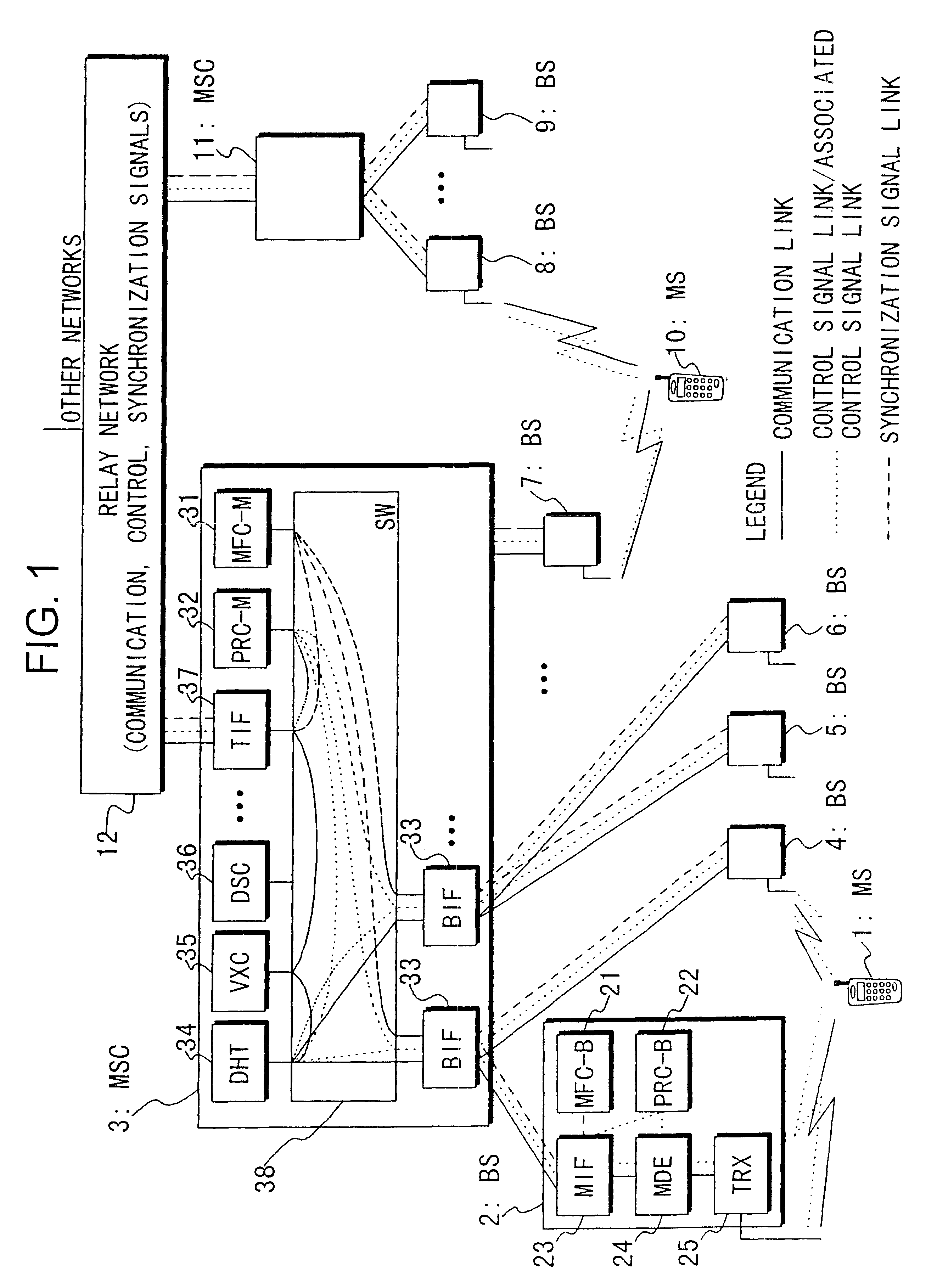
Below the structure of an embodiment of this invention will be described with reference to FIG. 1.

In FIG. 1, symbols 1 and 10 represent mobile stations (MS); symbols 2 and 4-9 base stations; and symbols 3 and 11 mobile switching station (MSC), and they form nodes in a mobile communication system.

Within the base station 2, symbol 23 represents an MSC interface (MIF) installed in the BS, and form a communication link and a signal link with a BS interface (BIF) 33 installed in MSC 3. A radio frame synchronizer (MFC-B) 21 installed in the BS determines frame synchronization in BS 2, and provides an operation reference clock to every section in BS 2.

A transceiver (TRX) 25 transmits and receives radio frames to and from the mobile station 1. A modulator / demodulator (MDE) 24 modulates and demodulates the radio frames and corrects errors thereof. A base station processor (PRC) 22 controls elements of the base station 2 on the basis of a predetermined control pro...


PUM


Abstract

Disclosed is a mobile communication system including a network constituted of at least one switching center and a plurality of base stations, and a mobile station which communicates with the base stations simultaneously. The system permits varying transmission delay between the switching center and the base stations according to the type of services available to the mobile station. The object of the present invention is to propose a communication which permits varying transmission delay according to the type of service currently employed, and to promptly recover a synchronization state even if an out-of-sync state happens. To attain the object, a memory means (mobile switching center processor 32) stores transmission delay characteristics corresponding to services which are available to the mobile station. Furthermore, a communication timing setting means (diversity handover trunk 34) determines the timing of communication for the base stations according to the transmission delay characteristic selected according to the service.

Description

The present relates to a method for handover, which is suitably used for a mobile communication system.TECHNICAL BACKGROUNDA diversity handover communication technique, wherein a mobile station moves across the boundary between cell sites of different base stations while continuing to communicate with the base stations, is described in Japanese patent application No. 6-106953. This application states a method in which a base station creates reliability information based on the state of radio frames received from a mobile station, and attaches the reliability information to each radio frames. Then, a diversity selection process is carried out in the communication network.Japanese patent application No. 6-210193 discloses another diversity handover method in which when communication is made between a mobile station and a superior system, frame identification information is used, to prevent the occurrence of skipping or overlapping of frames during diversity selection of the frames due...

Claims


Application Information

Patent Timeline
Patent Type & Authority Patents(United States)
IPC IPC(8): H04B7/26H04Q7/38H04Q7/24H04L7/08H04W36/00H04W36/12H04W36/14H04W36/18H04W36/36H04W36/38H04W56/00
CPCH04B7/022H04B7/2681H04W36/18H04W36/12H04W56/00H04B7/26
Inventor OHTANI, TOMOYUKITAMURA, MOTOSHINAKASHIMA, AKIKOSHIMIZU, HISASHISATOH, TAKAAKI
Owner KOKUSA ELECTRIC CO LTD
Why Eureka
Try Eureka