Flexible flat cable connector with sliding member

a flexible flat cable and sliding member technology, applied in the direction of electrical equipment, connection, coupling device connection, etc., can solve the problems of complicated slider operation, difficult insertion of flexible wiring member into the housing, and even more difficult insertion operation

Inactive Publication Date: 2002-11-05
AUTONETWORKS TECH LTD +2
View PDF5 Cites 17 Cited by
  • Summary
  • Abstract
  • Description
  • Claims
  • Application Information

AI Technical Summary

Benefits of technology

As described above, in the invention, in a connector for a flexible wiring member, a guiding mechanism is provided for guiding the slider such that when the slider is pushed into the housing with the flexible wiring member inserted therein, the slider slides in the first direction which is inclined in a direction of approaching the conductors of the flexible wiring member with respect to the inserting direction of the flexible wiring member, and subsequently slides in the second direction parallel to the inserting direction of the flexible wiring member. Therefore, there is an advantage in that while a wide insertion gap is secured for the flexible wiring member to facilitate the insertion in the state in which the slider has been pulled out, the connection between the flexible wiring member and the terminals can be reliably and stably maintained by the subsequent sliding in the first direction and the second direction.Further, as described above, the restraining portion is provided on the slider which is pushed into the housing, and the movement of the flexible wiring member in a direction opposite to the inserting direction of the flexible wiring member is restrained by abutment between the restraining portion and the reinforcing plate at the terminal of the flexible wiring member. Further, as the slider is pushed into the housing in a state in which the reinforcing plate is located on a further forward side in the inserting direction of the flexible wiring member than the restraining portion, the conductors of the terminal of the flexible wiring member are held at a position for contacting the conductor contacting portions of the terminals. Therefore, there are advantages in that it is possible to reliably effect the connection of the flexible wiring member, and that the state of its connection can be maintained satisfactorily.Still further, as described above, a connector according to the invention has a to-be-latched portion provided in a middle portion in the direction of width of a slider, and also has latching portions that engage with the to-be-latched portion and that are provided on the side of a housing. The engagement therebetween restrains the middle portion in the direction of width of the slider from bending at a pushing position and in a direction in which the slider is pushed. Thus, the connector of the invention has effects in that even when the width dimension of a flat wiring member is large, a favorable connection state is maintained over the entire region extending in the direction of width thereof.

Problems solved by technology

However, with the connector in which the slider is thus pushed in in a direction parallel to the inserting direction of the flexible wiring member, there is a drawback in that the slider which is pulled out toward this side constitutes a hindrance, so that the insertion of the flexible wiring member into the housing is difficult.
With the connector of the above-described publication, since the motion of rotating the slider is involved at the beginning of the pushing in or before completion of the pulling out of the slider, there is a drawback in that the operation of the slider becomes complicated.
Since the arrangement provided is such that a terminal of the flexible wiring member is inserted into the housing over the slider which is pulled out diagonally upward, the insertion operation is even more difficult, and it is very difficult to visually confirm the inserted state.
Hei5-69880 concerning a microfilm, the slider is arranged to slide in a diagonal direction over its entire stroke, and since it does not provide the operation of pushing in the slider in a direction parallel to the inserting direction of the flexible wiring member, it is difficult to reliably hold the flexible wiring member at a position of contact with connector terminals.
Furthermore, in a case where the slider is retained at its insertion-completed position in such a manner as to be incapable of moving backward, if there is any slight deviation in its retaining position, the force for restraining the flexible wiring member by the slider at that retaining position varies, so that there is a drawback in that the connection reliability declines by that margin.
Accordingly, due to the fact that the slider 190 is pushed in in a state in which the flexible wiring member 140 is in a semi-inserted state, there is a possibility of the occurrence of faulty connection.
There is a fear that contact failure occurs at worst.

Method used


Image

  • Flexible flat cable connector with sliding member
  • Flexible flat cable connector with sliding member
  • Flexible flat cable connector with sliding member

Examples


first embodiment

(First Embodiment)

Referring now to FIGS. 1 to 6B, a description will be given of a first embodiment of the invention.

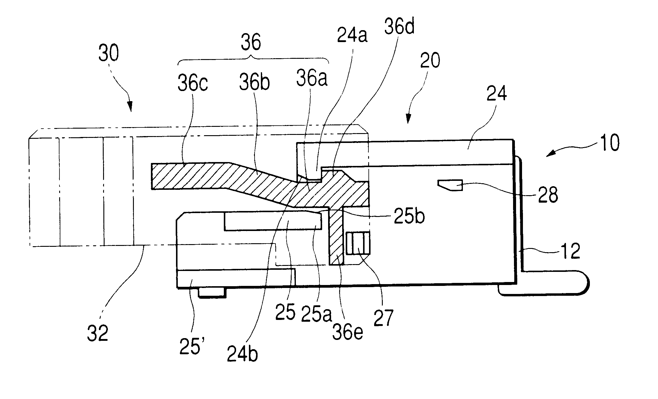
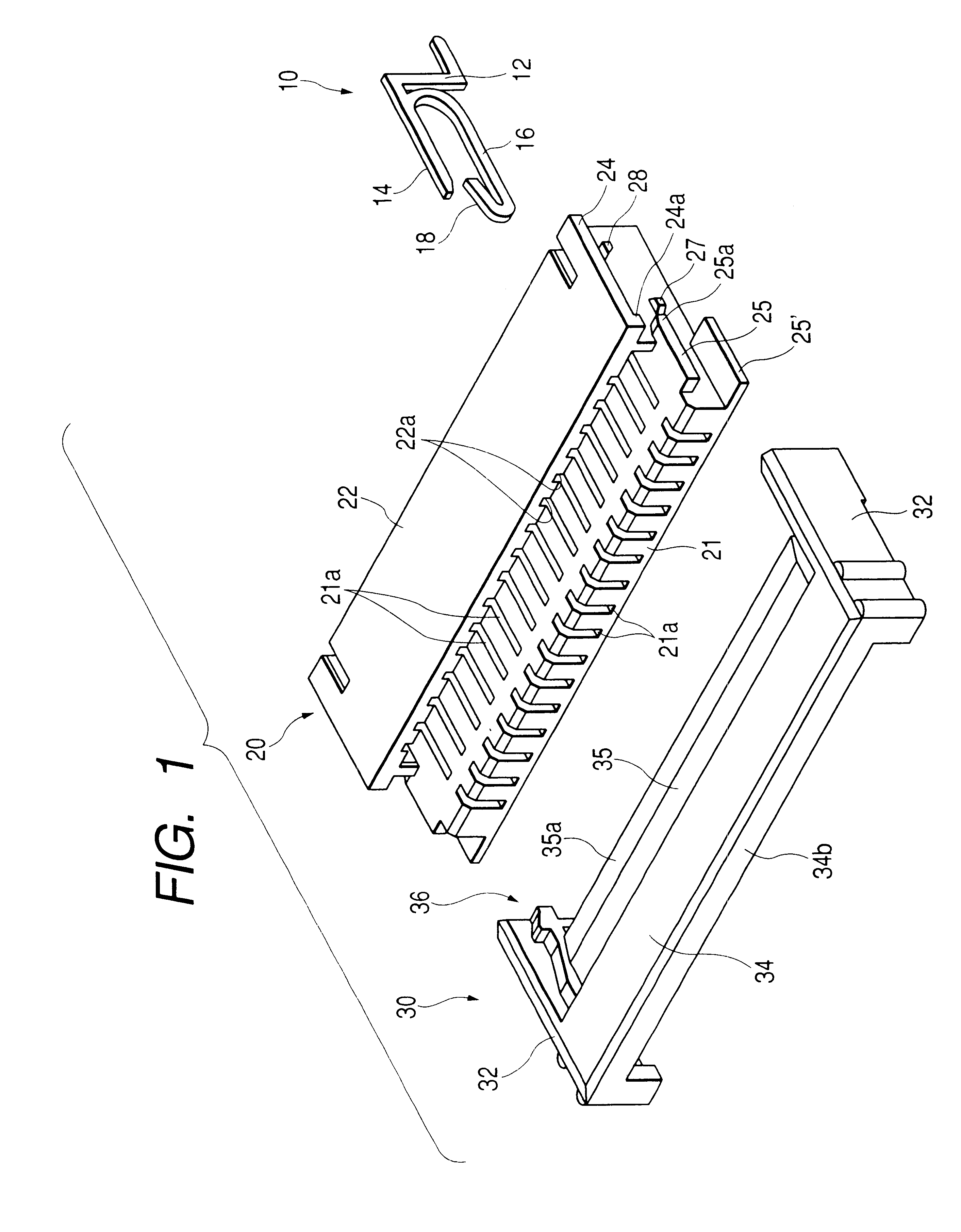
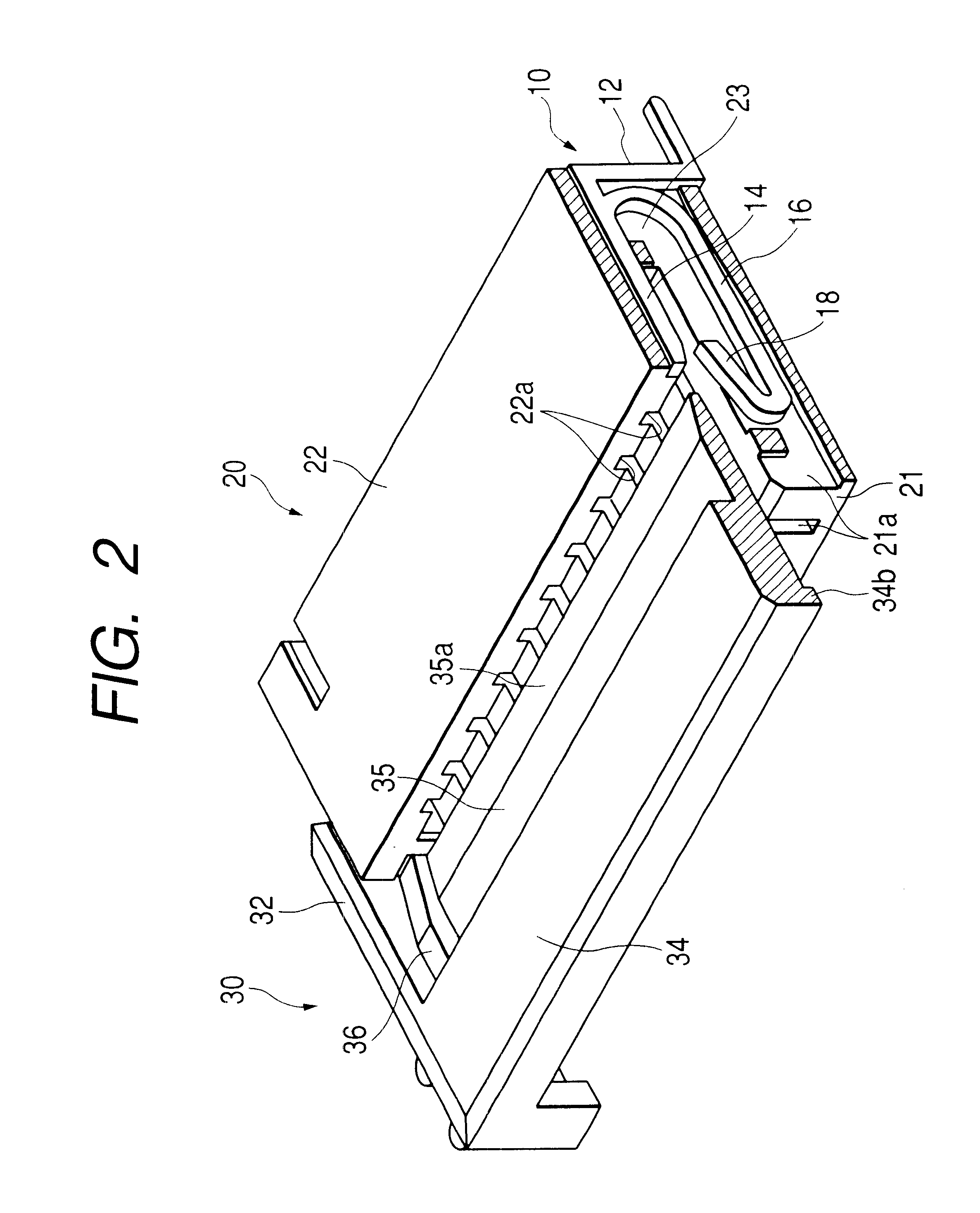
The illustrated connector has a multiplicity of terminals 10, a housing 20 for supporting them, and a slider 30 fitted to the housing 20.

Each terminal 10 integrally comprises a substantially L-shaped leg portion 12 formed of a conductive material such as a metal and mounted on a substrate; an upper horizontal portion 14 extending horizontally from an upper end of this leg portion 12; a lower horizontal portion 16 branched off downwardly from a proximal end of this upper horizontal portion 14 and extending parallel to the upper horizontal portion 14; and a conductor contacting portion 18 which reverses from an end of this lower horizontal portion 16 at an acute angle. A lower surface of a front terminal of the upper horizontal portion 14 is formed as an inclined surface which is oriented in such a manner as to become higher toward the front.

The overall housing 20 is in...

second embodiment

(Second Embodiment)

It should be noted, however, that the guide portion 36 in the invention may not necessarily be a protrusion, and may be formed as a groove, and a projection for fitting in this groove may be provided on the housing 20 side as a restraining portion. In addition, similar sliding action can be also obtained by providing a guide portion corresponding to the guide portion 36 on the housing 20 side and by providing a restraining portion for restraining it on the slider 30 side. An example of it will be shown in FIGS. 7 to 9 as a second embodiment.

In the drawings, a pair of guide portions 29 which are protrusions are respectively formed on both side surfaces of the housing 20, and each of the guide portions 29 has in a continuous manner an upper horizontal portion 29a, an inclined portion (first guide portion) 29b, and a lower horizontal portion (second guide portion) 29c, these portions being arranged in that order from the front end side of the housing. Further, a pair...

third embodiment

(Third Embodiment)

Referring now to FIGS. 12 to 17B, a description will be given of a preferred embodiment of the invention.

The illustrated connector has a multiplicity of terminals 110, a housing 120 for supporting them, and a slider 130 fitted to the housing 120.

Each terminal 110 integrally comprises a substantially L-shaped leg portion 112 formed of a conductive material such as a metal and mounted on a substrate; an upper horizontal portion 114 extending horizontally from an upper end of this leg portion 112; a lower horizontal portion 16 branched off downwardly from a proximal end of this upper horizontal portion 114 and extending parallel to the upper horizontal portion 114; and a conductor contacting portion 118 which reverses from an end of this lower horizontal portion 116 at an acute angle. A lower surface of a front terminal of the upper horizontal portion 114 is formed as an inclined surface which is oriented in such a manner as to become higher toward the front.

The overa...


PUM


Abstract

A connector in which a slider 30 is pushed into a housing 20 in a state in which a terminal of a flexible wiring member 40 has been inserted in the housing 20, thereby holding the terminal of the flexible wiring material 40 at a position where its conductors are brought into contact with terminals 10. A guiding mechanism for the slider 30, including a guide portion 36 and the like, is provided. At the time of the pushing of the slider, the slider 30 is guided such that after being slid in a first direction which is inclined in the direction of approaching conductors of the wiring member 40 with respect to an inserting direction of the wiring member, the slider 30 is slid in a second direction parallel to the inserting direction of the wiring member.

Description

1. Technical FieldThe present invention relates to a connector to which is connected a terminal of a flexible wiring member, such as a flexible flat cable (FFC) in which a plurality of conductors are arranged parallel to each other in the longitudinal direction and a flexible printed circuit (FPC) having a circuit printed on a flexible base material.2. Related ArtConventionally, as a means for connecting a terminal of a flexible wiring member to, for example, a circuit board, one is known in which a connector to which the terminal is connectable is mounted on a substrate. In such a connector, in view of the fact that the flexible wiring member which is connected is liable to deflect and the insertion is difficult, an arrangement is provided such that the terminal of the flexible wiring member is made insertable in a housing in a state in which the resistance is practically nil, and after the insertion a slider is pushed into the housing in a direction parallel to the inserting direc...

Claims


Application Information

Patent Timeline
Patent Type & Authority Patents(United States)
IPC IPC(8): H01R12/24H01R12/00H01R12/08H01R12/79H01R12/89
CPCH01R12/79H01R12/89
Inventor INOUE, TAKUYA
Owner AUTONETWORKS TECH LTD
Why Eureka
Try Eureka