Contact assembly

a technology of contact and assembly, applied in the direction of contacts, switches with unconnected briding contacts, electrical devices, etc., can solve the problems of adding manufacturing complexity and cost, and achieve the effect of easy visual detection of orientation, increased number of contacts within a given volume, and simplified assembly process

Inactive Publication Date: 2002-11-19
ROCKWELL AUTOMATION
View PDF6 Cites 18 Cited by
  • Summary
  • Abstract
  • Description
  • Claims
  • Application Information

AI Technical Summary

Benefits of technology

In contrast with contact assemblies in which the fixed contacts are U-shaped, the L-shaped contacts in accordance with the present invention make it possible to accommodate more pairs of fixed contacts in a given volume. It also makes it possible to design the insulating body so that contacts can only be inserted i...

Problems solved by technology

If a movable contact is displaced against a portion of the surface of a fixed contact which does not have the appropriate surface treatment rapid wear and hence contact fail...

Method used


Image

  • Contact assembly
  • Contact assembly
  • Contact assembly

Examples


Embodiment Construction

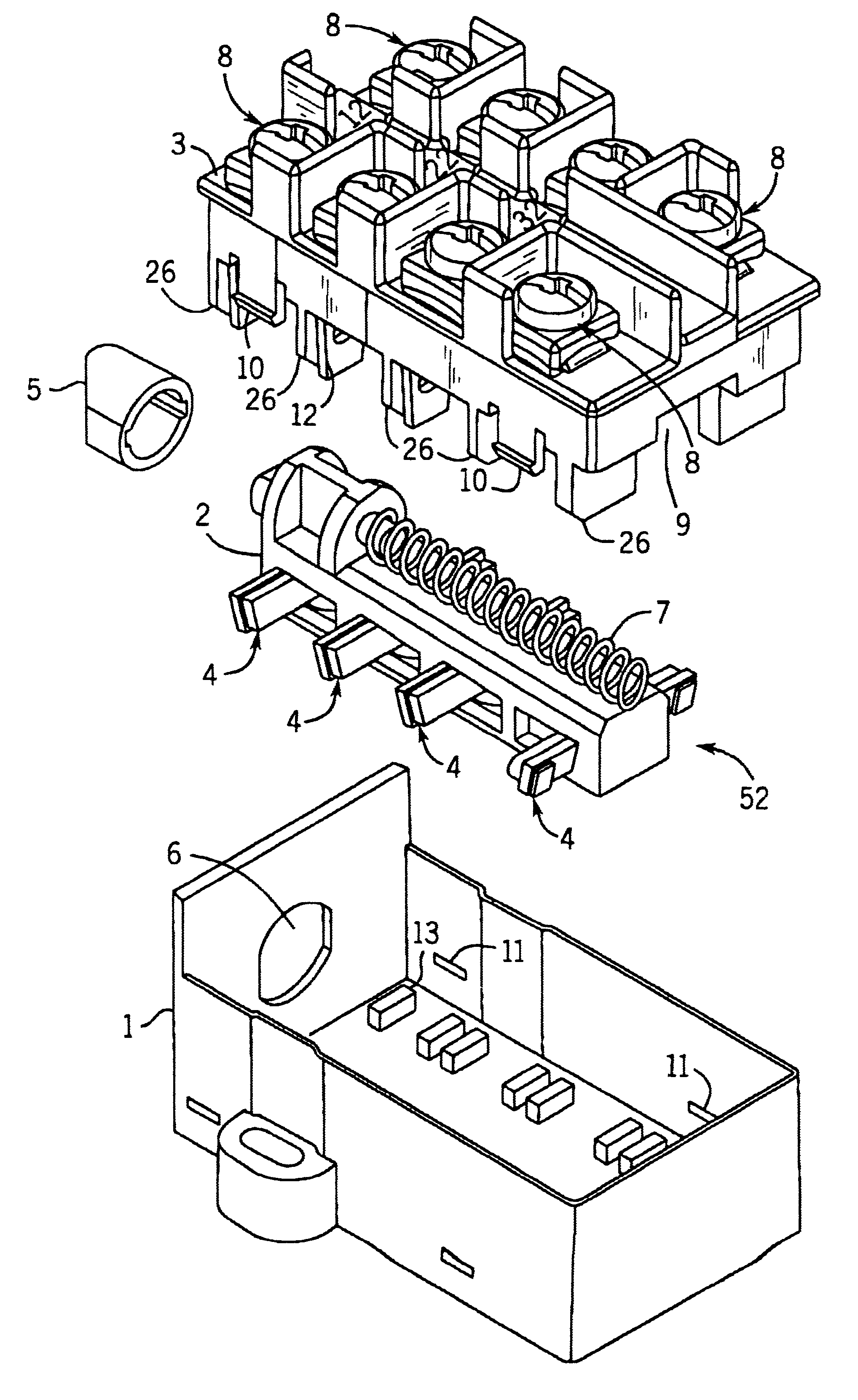
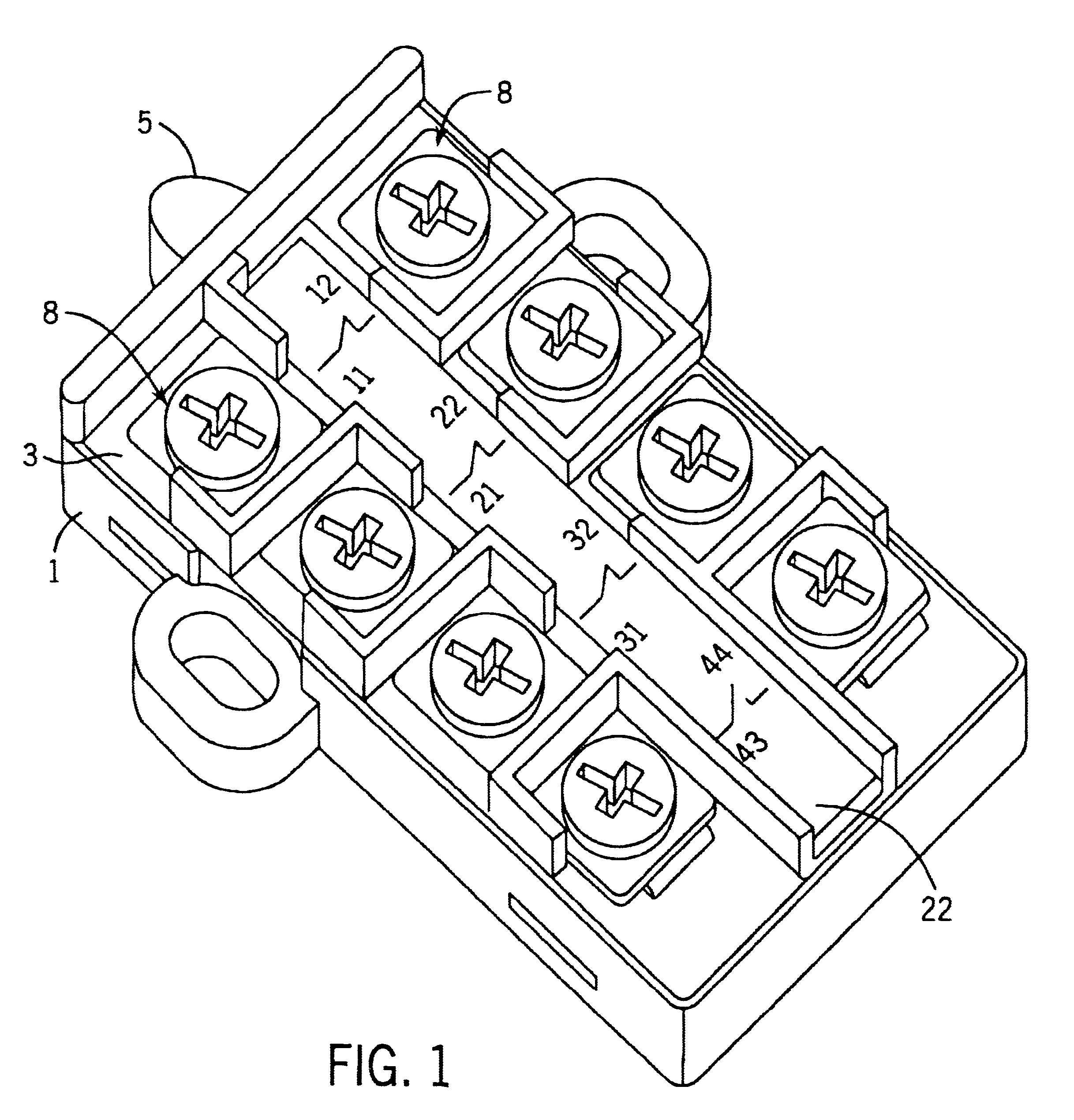
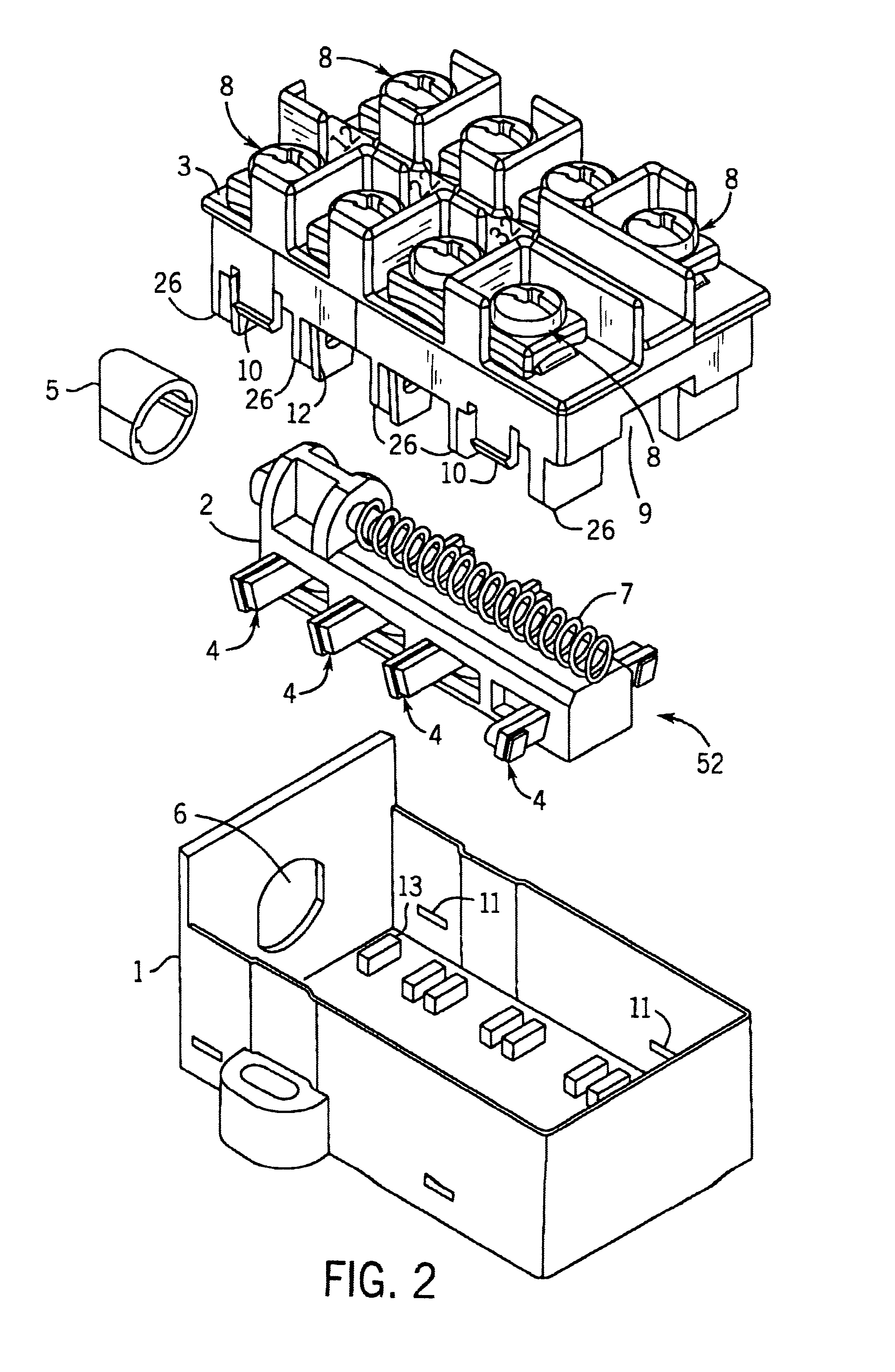
Referring to FIGS. 1 and 2, the illustrated contact assembly comprises a casing, an actuator or actuator assembly 52 incorporating a carrier 2, a fixed contact assembly including an insulating body 3. The actuator assembly carries four movable contacts 4 and the carrier 2 engages a nose 5 which projects through an aperture 6 in the casing 1. A compression spring 7 biases the carrier 2 so as to push the nose 5 outwards relative to the aperture 6. The insulating body 3 supports four pairs of fixed contacts 8.

The components shown in FIG. 2 are assembled by dropping the actuator assembly including carrier 2 into the casing 1 such that the nose 5 projects through the opening 6 and then dropping the insulating body 3 over the actuator assembly. The underside of the insulating body 3 defines a recess 9 which accommodates the actuator assembly. Resilient hooks 10 defined by the insulating body 3 engage in apertures 11 defined in the casing 1 so as to retain the assembled components in posit...


PUM


Abstract

A contact assembly comprising a plurality of pairs of spaced apart fixed contacts supported in an electrically insulating body, an actuator displaceable relative to the body between first and second positions, and a plurality of movable contacts mounted on the actuator. Each movable contact is positioned on the actuator so as to interconnect the contacts of one of the pairs of fixed contacts only when the actuator is in one of the first and second positions. Each fixed contact has two limbs defining an L-shape, one limb defining a single leg which extends through an aperture formed in a partition defined by the body and the other limb extending to one side of the leg to define a head supporting a terminal for gripping a wire. Each movable contact is displaceable into contact with the leg of each of the respective pairs of fixed contacts on the side of the leg from which the head extends and on the side of the partition remote from the head.

Description

The present invention relates to a contact assembly and in particular to a contact assembly in which pairs of spaced apart fixed contacts are supports in an electrically insulating body and sets of movable contacts are displaceable relative to the insulating body so as to either interconnect or disconnect the contacts of each of the pairs of fixed contacts.In one known contact assembly, three pairs of spaced apart fixed contacts are supported in an electrically insulating body. An actuator is displaceable relative to the body and carries three movable contacts. Each of the three movable contacts is associated with one of the pairs of fixed contacts. The actuator is displaceable between two positions. For each of the movable contacts, when the actuator is in one of the two positions the movable contact bears against the associated pair of fixed contacts so as to electrically interconnect them whereas when in the other of the two positions the movable contacts is spaced from the assoc...

Claims


Application Information

Patent Timeline
IPC IPC(8): H01H1/00H01H1/58H01H11/06H01H11/04H01H11/00H01H1/20H01H1/12H01H31/24
CPCH01H1/5855H01H11/06H01H1/20H01H1/2083H01H11/0012H01H2011/062H01H2300/042
Inventor MOHTASHAM, MEHDI
Owner ROCKWELL AUTOMATION
Why Eureka
Try Eureka