Head protection air bag apparatus

a technology for air bags and head protection, which is applied in the direction of superstructure sub-units, vehicle arrangements, vehicle components, etc., can solve the problems of increasing the number of air bags, increasing the number of components of the air bag, and increasing the number of processes

Inactive Publication Date: 2002-11-26
TOYODA GOSEI CO LTD
View PDF15 Cites 88 Cited by
  • Summary
  • Abstract
  • Description
  • Claims
  • Application Information

AI Technical Summary

Benefits of technology

Another aspect of the invention is to provide a head protection air bag apparatus in which an opening operation of a lower edge portion of an air bag cover, which abuts an upper edge portion of a pillar garnish, is made free of restriction so that development and inflation of the air bag can be completed quickly.
In the second head protection air bag apparatus, it is arranged that the upper edge portion of the air bag cover covers the interior side of a lower edge portion of the roof head lining that is disposed above the air bag cover. That is, the upper edge portion of the air bag cover is disposed on the interior side of the vehicle, relative to the lower edge portion of the roof head lining, and abutted to the roof head lining. In such an arrangement, the roof head lining can be mounted in a vehicle even when a terminal treatment such as trimming of the roof head lining lower edge portion is insufficient. This is because the upper edge portion of the air bag cover covers the roof head lining lower edge portion. As a result, the terminal treatment of the roof head lining lower edge portion can be easily performed through this design. A decrease of the appearance of the roof head lining can also be controlled.

Problems solved by technology

Accordingly, it takes a long time for the gas for inflation to reach the terminal end of the air bag, which is located away from the inflator.
In this case, it takes a long time for the gas for inflation to reach the air bag terminal end.
Preparing the cover material, however, increases the number of components of the air bag as well as the number of processes for installing the air bag apparatus in a vehicle.
As a result, in the conventional head protection air bag apparatus, the door portion is difficult to open smoothly and thereby, there is a need for improving the quick development and inflation of the air bag.
Thus, the use of the assist grip in the head protection air bag apparatus does not increase the number of components mounted in a vehicle.

Method used


Image

  • Head protection air bag apparatus
  • Head protection air bag apparatus
  • Head protection air bag apparatus

Examples


first embodiment

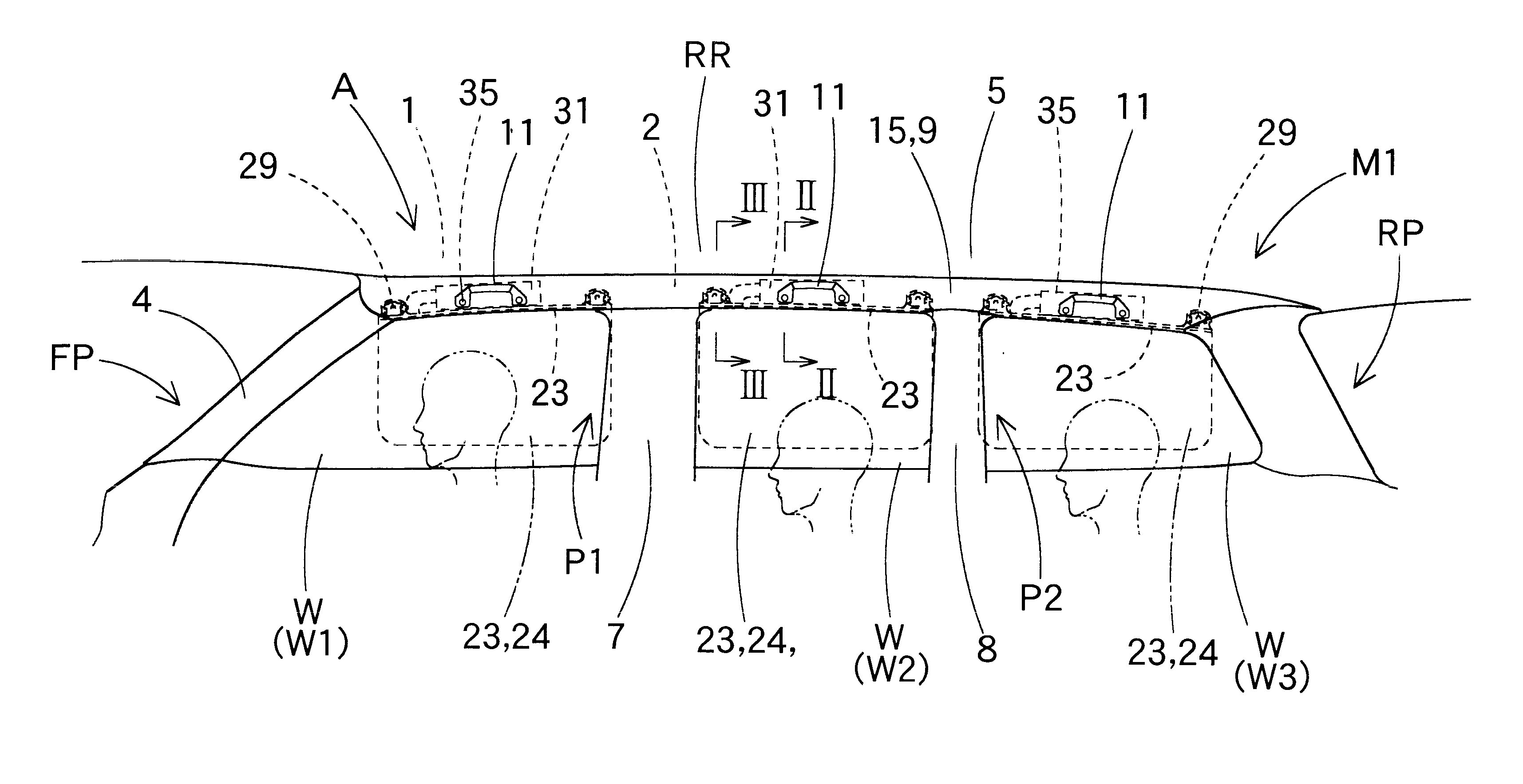
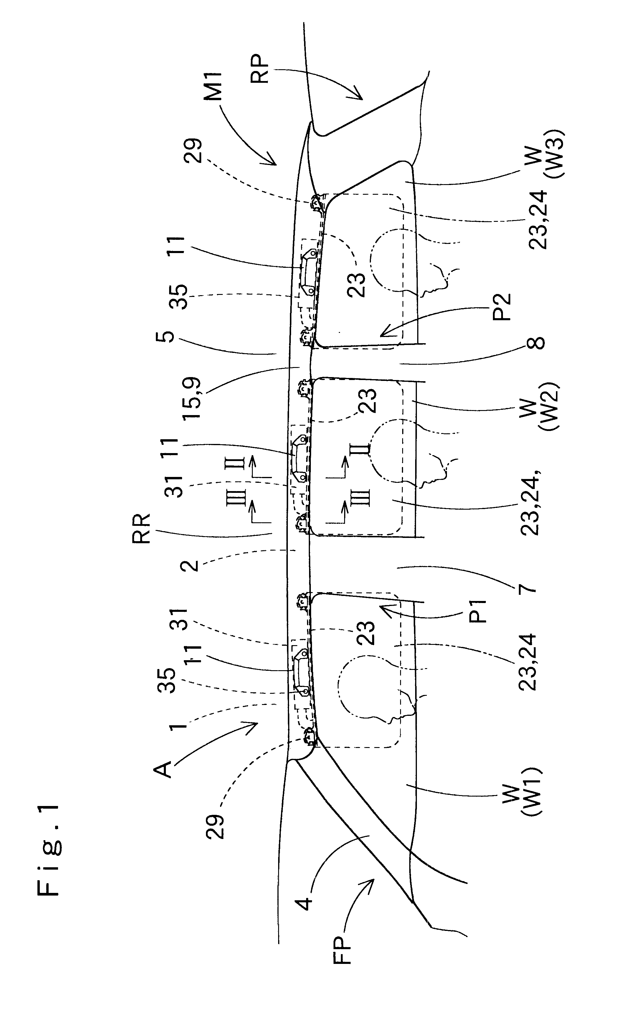
A head protection air bag apparatus Ml shown in FIGS. 1 to 4 in the first embodiment is mounted in a vehicle having three rows of seats, as shown in FIG. 1. The head protection air bag apparatus M1 comprises three folded air bags 23. These air bags 23 are provided in the upper edge side of the periphery of an opening W of a door or a window portion on the interior side of a vehicle. Specifically, the above air bags 23 are provided in a roof side rail portion RR, which extents from a front pillar portion FP through a first and second middle pillar portions P1 and P2 to the vicinity of a rear pillar portion RP.

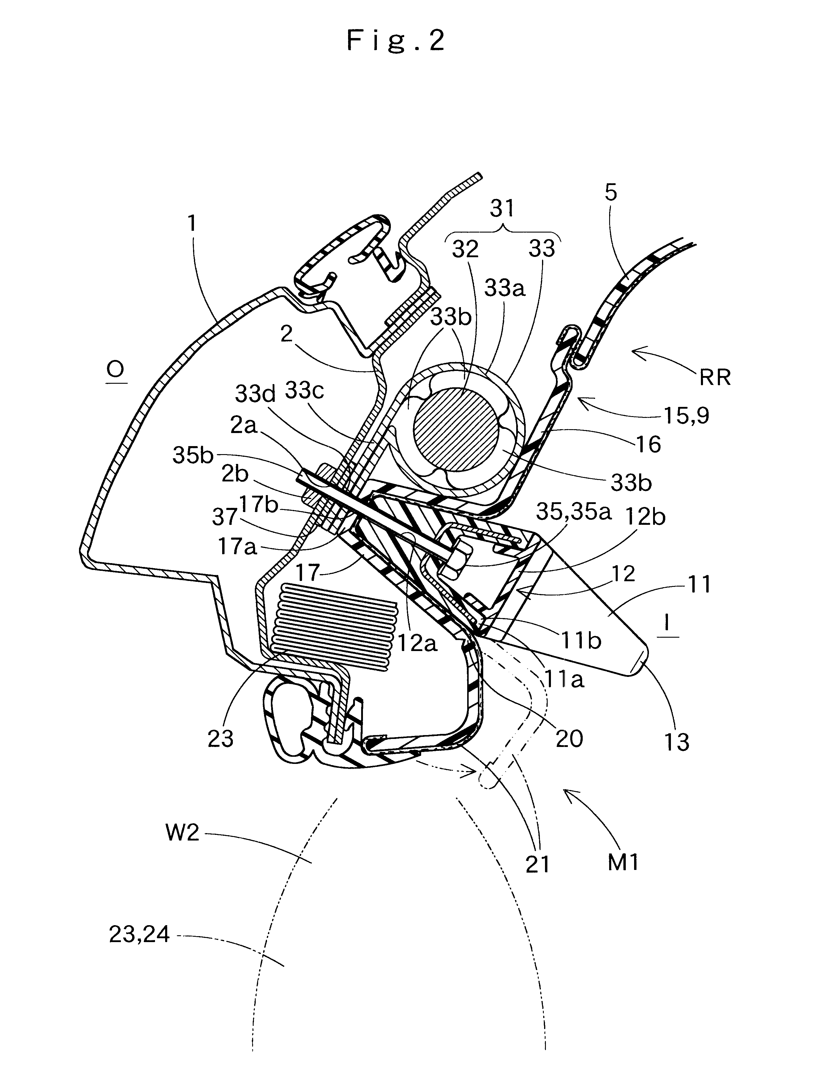
The head protection air bag apparatus M1 comprises an air bag 23, an inflator 31, an installation bracket 28, an air bag cover 15 and an assist grip 11.

Each air bag 23 is provided so as to cover respective openings W1, W2, and W3 of each window portion, as shown in FIGS. 1 to 4. Each air bag 23 is folded and housed on the upper edge side of a periphery of respective openings W1,...

second embodiment

Next, the head protection air bag apparatus M2 in the second embodiment shown in FIGS. 7 to 12 will be described. In this air bag apparatus M2, an air bag cover 15A is formed into one body on the lower edge side of the roof head lining 5.

In the air bag apparatus M2, a structure of an air bag 43, an inflator 51, an assist grip 11A (11A1, 11A2 and 11A3) and a portion of a part of the air bag cover 15A is somewhat different from the first embodiment. For example, the air bag cover 15A is formed into one body with the roof head lining 5.

The air bag 43 is woven into a shape of a bag, as was the case in the first embodiment. A single air bag 43, however, is used to cover the interior side of a vehicle from a vicinity of the front pillar portion FP to the rear pillar portion RP, as shown in FIGS. 7 and 12. The air bag 43 comprises two gas flow portions 45 and 46, which are disposed in a vicinity of the front and rear ends on the upper edge side of the air bag 43. A main air bag body portio...

third embodiment

In a head protection air bag apparatus M3 in the third embodiment shown in FIGS. 13 to 19, one folded air bag 23A is provided in the front-rear direction on the interior side of a vehicle, as shown in FIG. 13. Specifically, the air bag 23A is provided in a periphery on the upper edge side of an opening W of a door or a window portion on the interior side of a vehicle, that is, in a roof side rail portion RR from a front pillar portion FP through a center pillar portion CP, which is a middle pillar portion, to a vicinity of a rear pillar portion RP.

The head protection air bag apparatus M3 comprises the air bag 23A, an inflator 31, an installation bracket 28, an air bag cover 15 and an assist grip 11.

The head protection air bag apparatus M3 in the third embodiment is mounted in a vehicle in which the middle pillar portion comprises a line of the center pillar portion CP. The head protection air bag apparatus M3 comprises one air bag 23A and one inflator 31, and the air bag cover 15 is...


PUM


Abstract

A head protection air bag apparatus comprises an air bag, an air bag cover for covering the air bag, an inflator for supplying the air bag with a gas for inflation, and an assist grip. The inflator is fixed to a body of a vehicle at a location toward the exterior side of a vehicle relative to the assist grip. The assist grip is provided on its exterior surface with a cover layer having the characteristic of a cushion, so that an impact with the inflator will be cushioned by the assist grip.

Description

This application claims priority from Japanese application 2000-138958 filed May 11, 2000, and Japanese application 2000-157293 filed May 26, 2000, which are hereby incorporated by reference into this application.1. Field of the InventionThe present invention relates to a head protection air bag apparatus mounted in a vehicle. The head protection air bag apparatus is provided with a folded air bag in a predetermined location on the interior side of a vehicle.2. Description of the Related ArtConventionally, in this kind of head protection air bag apparatus, an air bag is folded to be housed on an upper edge side of the periphery of an opening on the interior or inner side of a vehicle, that is, in a periphery from a front pillar portion to a roof side rail portion, as described in the Japanese Laid-Open Patent Application No. Hei 11-321532.A gas for inflation supplied by an inflator flows into the air bag from either its front end side or rear end side. Accordingly, it takes a long t...

Claims


Application Information

Patent Timeline
Patent Type & Authority Patents(United States)
IPC IPC(8): B60R21/20B60N2/48B60R21/055B60R21/02B60R21/26B60R13/02B60R21/213
CPCB60N2/4876B60R21/213B60R13/025B60R21/055B60R21/26B60R2013/0281
Inventor TAJIMA, HIROYUKITOTANI, CHIHARUSAKUMA, YOSHIYUKINAGATA, TAKUJIOSAWA, YASUYUKI
Owner TOYODA GOSEI CO LTD
Why Eureka
Try Eureka