Integrated bi-modal wheel assembly

a technology of integrated bi-modal wheels and wheels, which is applied in the direction of transportation and packaging, toys, and locomotives, can solve the problems of not providing for the automatic inflation and deflation of pneumatic tires, far proven very costly to construct and maintain, and complicated wide range of conversion and adaptation devices

Inactive Publication Date: 2006-07-18
TREMBLAY RICHARD B
View PDF26 Cites 20 Cited by
  • Summary
  • Abstract
  • Description
  • Claims
  • Application Information

AI Technical Summary

Benefits of technology

[0025]The objective of the invention is to provide a new and improved apparatus set that, when applied to a wide variety of transit and freight vehicles, and through simple maneuvering by the vehicle operator, will quickly and efficiently transition said vehicles from a road-way transport mode to a railway transport mode, and conversely, from a railway transport mode to roadway transport mode without any requirement to change vehicle configuration. The apparatus set is a combination of a railway wheel, and a roadway wheel and pneumatic tire assembly mounted concentrically and closely coupled on a single hub, spindle and axle assembly.
[0026]The railway wheel is a lightweight design and made of steel. The railway wheel's outside face is uniquely shaped to couple to and rest against the inside face of the pneumatic tire. The railway wheel tread is shaped with a 20 degree slope (taper) that is standard to the North-American rail transportation industry. The railway wheel is configured with a shallow flange on the inside edge of the wheel and at the extremity of the wheel's diameter to assure correct wheel-to-track engagement and alignment while operating in the railway transport mode.
[0029]The pneumatic tire component of the roadway wheel and pneumatic tire assembly will be mounted such that the tire's inside face and sidewall will be in contact and rest against the contoured outside face of the railway wheel. The pneumatic tire is approximately three (3) inches greater in diameter that the diameter of the railway wheel. Therefore, the inside face and sidewall of the pneumatic tire near the extremity of tire's diameter is uniquely positioned to slightly contact the outside edge of the railway track flange, and to thereby effectively provide added stability to the wheel-to-track engagement and alignment while operating in the railway transport mode.
[0031]The hub and spindle assembly that carries the apparatus set is machined and ported to provide for the embedment of compressed air passages, glands, seals, and other features for the adaptation of a commercially available automatic tire inflation and deflation system. The function of the automatic tire inflation and deflation system is to provide for the rapid inflation of the pneumatic tire for operating in the roadway transport mode, and raising and holding the railway wheel free and clear of the paved roadway surfaces. Conversely, the automatic tire inflation and deflation system will provide for the rapid deflation of the pneumatic tire for operating in the railway transport mode and lowering and keeping the railway wheel engaged and in full contact with the railway track.

Problems solved by technology

This patent does not provide for the automatic inflation and deflation of the pneumatic tire and does not position the pneumatic tire adjacent to and in contact with the railway wheel to provide for assisting wheel alignment with the steel track while operating in the railway transport mode.
The special curb-wall infrastructures of the invention are presently installed in a very few international urban metropolitan areas and have thus far proven very costly to construct and maintain.
As can be readily concluded from the above discussion, this wide assortment of conversion and adaptation devices are complicated by their need to incorporate raising and lowering mechanisms or to provide a separate undercarriage to allow for the second transportation mode.
This complexity adds fabrication costs, increases vehicle weight and maintenance, reduces reliability and may adversely impact operational safety.
Such systems are also complex to operate, particularly when making roadway-railway transitions.

Method used


Image

  • Integrated bi-modal wheel assembly
  • Integrated bi-modal wheel assembly
  • Integrated bi-modal wheel assembly

Examples


Embodiment Construction

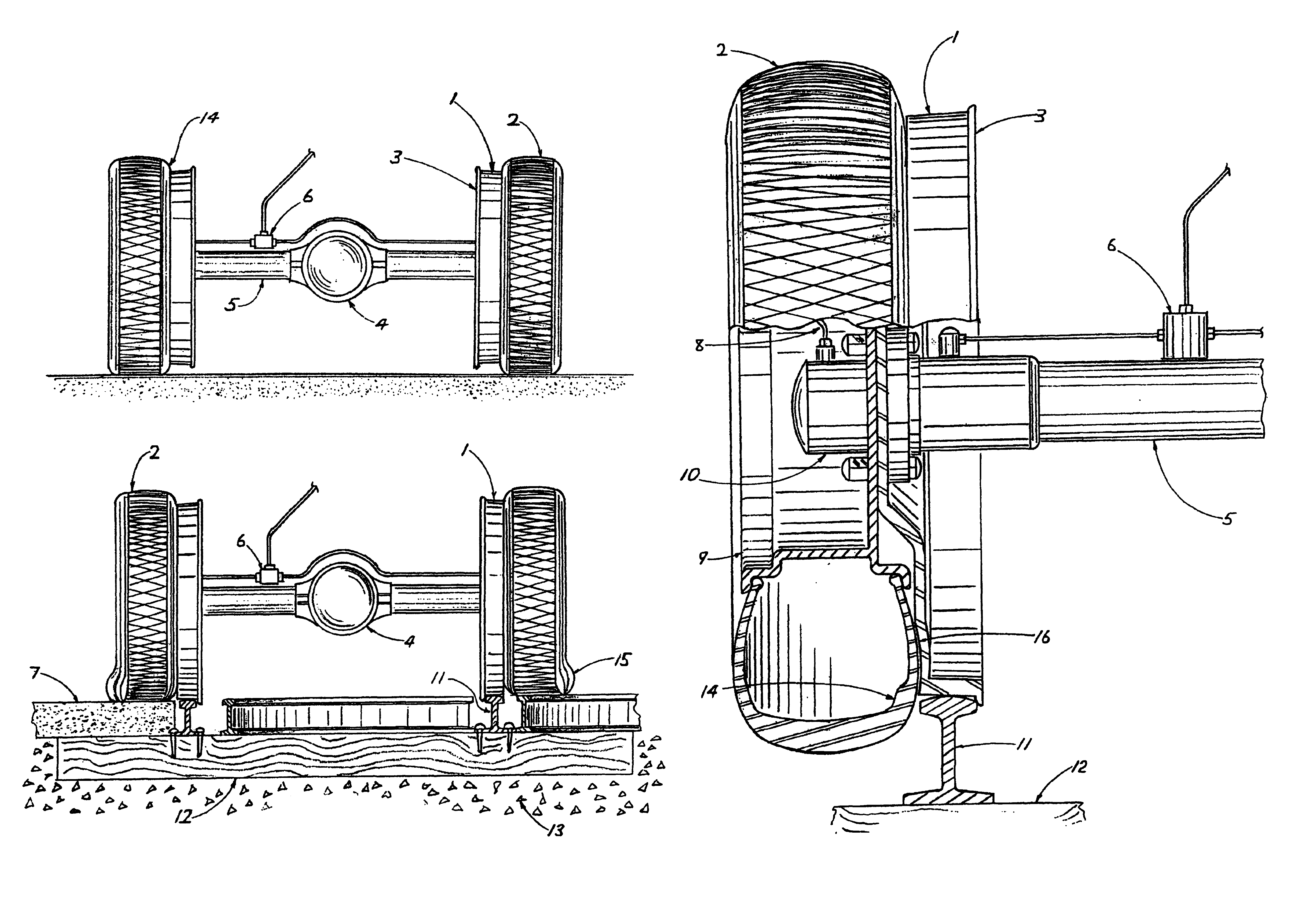
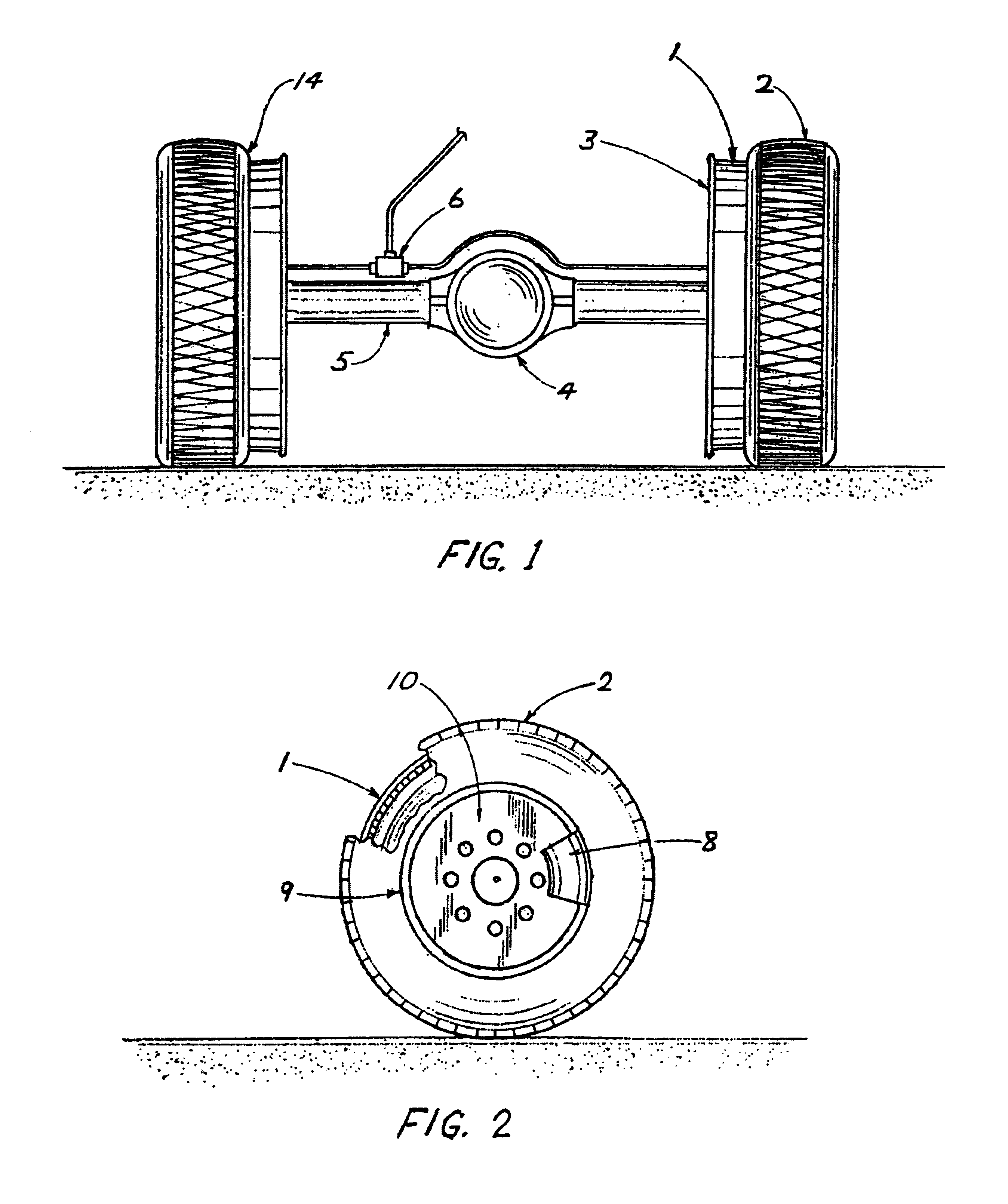
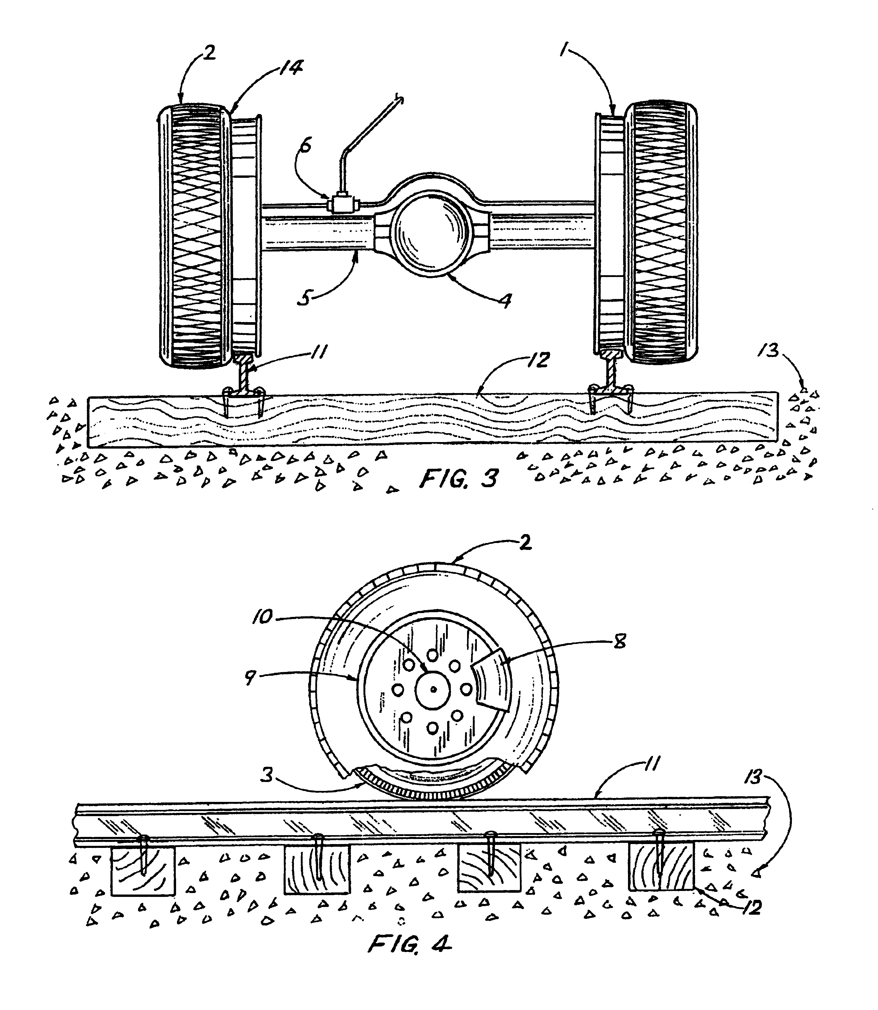
[0039]Referring to FIG. 1 through FIG. 7, this invention is for an Integrated Bi-modal Wheel Assembly for use with road-rail adaptive vehicles. Such vehicles are to be used with freight and mass transit systems. The invention is also applicable in other dual use systems (civilian and military), for transporting troops, ordinance, and / or material to unknown, unpredictable destinations, via road and rail, to simplify logistics, reduce costs, schedules, time-to-destinations, and other efficiencies. The concept can also include exclusive custom / luxury transit vehicles, as well as a mass market SUV and other vehicles designed for transport of people or freight via rail, paved roads or rustic roads.

[0040]In the preferred embodiment of this invention, FIG. 1 comprises a pair of integrated road-rail wheels 1&2, each integrated wheel having road tire 2, rail wheel 1, and in FIG. 2, wheel cover 8 for known automatic inflate / deflate system valves and porting, steel roadway wheel 9, and spindle...


PUM


Abstract

This invention relates generally to vehicular transportation for humans and freight by roadway and railway. More specifically, this invention relates to a unique combination of a novel roadway wheel and pneumatic tire assembly, incorporating a known automatic inflate-deflate system and a novel lightweight railway wheel; both wheels then coupled and concentrically assembled on a common axle with special provisions for the known automatic inflation and deflation of the pneumatic roadway tire.

Description

BACKGROUND DESCRIPTION OF THE INVENTION[0001]1. Field of the Invention[0002]This Integrated Bi-modal Wheel Assembly (IBMWA), invention relates generally to freight transport and mass transport of humans by roadway and railway. The transport of humans and freight on railways is a well established form of surface transportation, and is performed by a broad set of railway vehicles that are engineered, designed and manufactured to operate exclusively on steel railway tracks—the most common being the Standard Gauge (56.5 in. between inside rail flanges) parallel steel railway infrastructure common throughout North America. The transport of humans and freight on roadways is also a well established form of surface transportation, and is performed by a variety of roadway vehicles that are engineered, designed and manufactured to operate exclusively on many classes of improved roadways.[0003]More specifically, this invention relates to integrated assemblies of custom roadway wheels and custo...

Claims


Application Information

Patent Timeline
Patent Type & Authority Patents(United States)
IPC IPC(8): B61C11/00B60B17/00
CPCB60B11/02B60B37/00B60B19/02B60B17/0068
Inventor TREMBLAY, RICHARD B.LARKIN, JAMES D.
Owner TREMBLAY RICHARD B
Why Eureka
Try Eureka