Seal apparatus for a water pump, rotation-support apparatus for a water pump, and a water pump

Inactive Publication Date: 2002-11-26
NSK LTD
View PDF23 Cites 28 Cited by
  • Summary
  • Abstract
  • Description
  • Claims
  • Application Information

AI Technical Summary

Problems solved by technology

However, with the aforementioned mechanical seal 10, obtaining a perfect seal is difficult, and when if friction heat is generated on the seal surface of this mechanical seal 10, the coolant water, which contains chemical matter such as an anti-freeze agent or anti-rust a

Method used


Image

  • Seal apparatus for a water pump, rotation-support apparatus for a water pump, and a water pump
  • Seal apparatus for a water pump, rotation-support apparatus for a water pump, and a water pump
  • Seal apparatus for a water pump, rotation-support apparatus for a water pump, and a water pump

Examples


Embodiment Construction

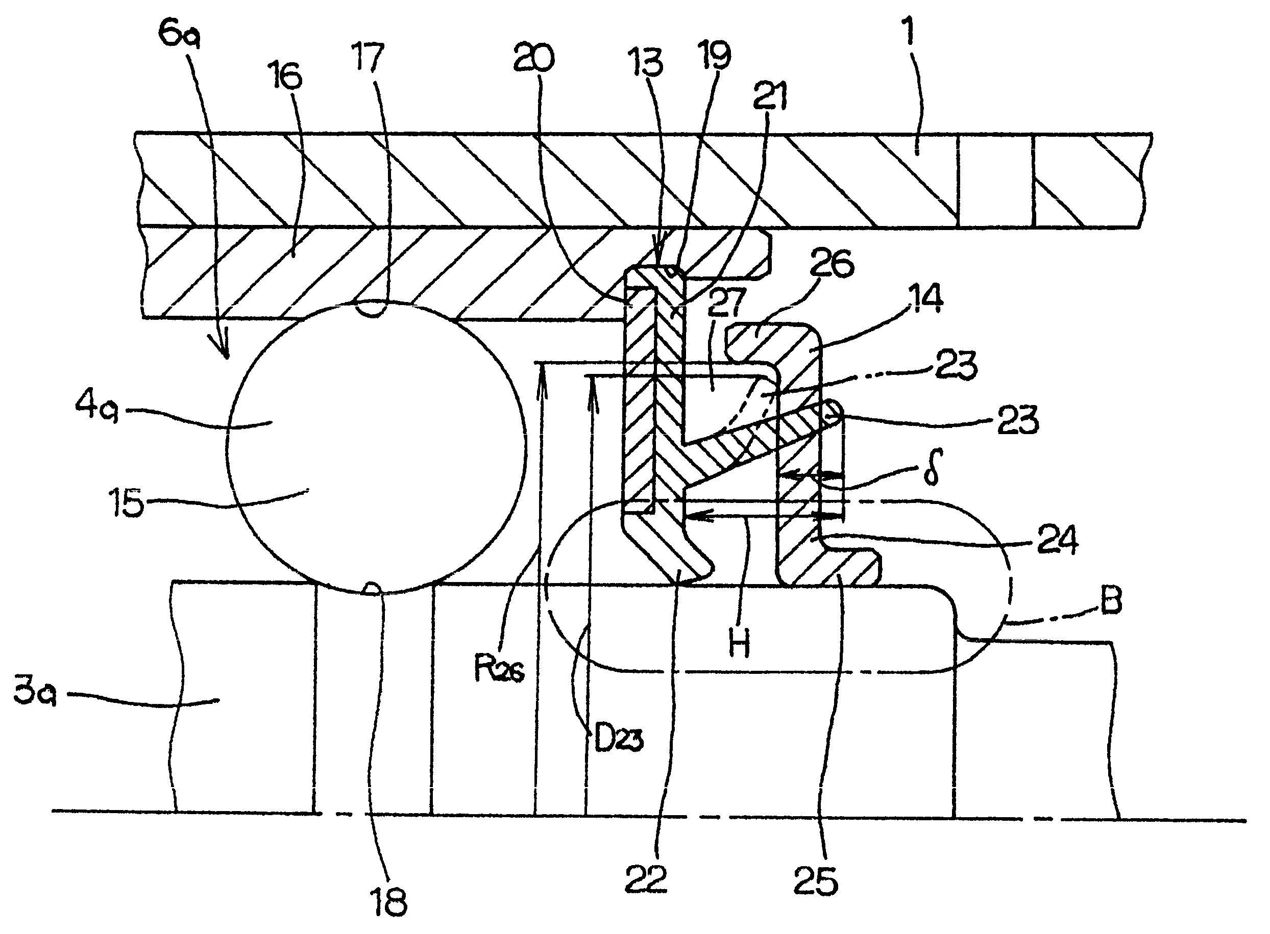
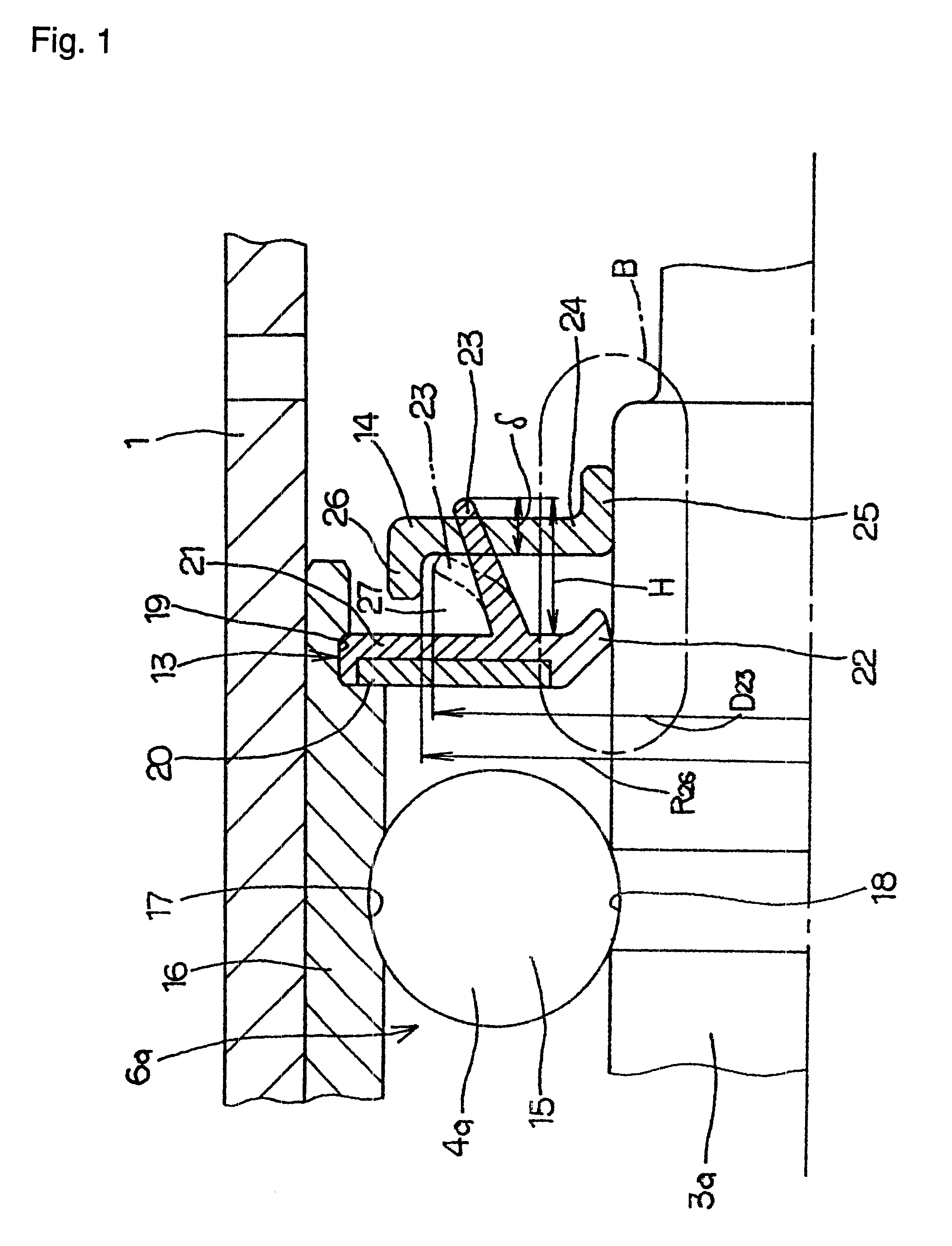
FIG. 1 and FIG. 2 show a first example of the embodiment of the present invention. This example is characterized by making it difficult for steam or hot water that passes the mechanical seal 10 to get inside the rolling-bearing unit 6 including the plurality of rolling elements (balls) 15, by adequately regulating the shape and dimensions of the seal ring 13 and singer 14 that are located in the middle section of the rotating shaft 3a further toward the outside than the mechanical seal 10 (see FIG. 4). The overall construction of the water pump and the construction and function of other sections are substantially the same as that of a conventional water pump, including the construction shown in FIG. 4, so drawings and explanations of identical sections will be omitted or simplified, and only the sections that are features of this invention or sections that were not previously explained will be explained here.

In order to construct the ball bearing 4a that is part of the aforementione...


PUM


Abstract

A seal apparatus is comprised of a seal ring 13 and a singer 14 in combination to prevent foreign matter from progressing into the rolling bearing 6a. The amount of compression delta of the second seal lip 23, which occurs when the tip edge of the second seal lip 23 of the seal ring 13 comes in contact with the outside surface of the singer 14, is at least 1/10and up to 7/10the height of the second seal lip 23 in the free state. In addition, the roughness of a portion of the outside surface of the singer 14 which the tip edge of the second seal lip 23 comes in sliding contact with is from 0.2mum to 2.0mum in the arithmetic mean Ra, or is from 0.8 mum to 8.0 mum in the maximum height Ry. Consequently, a structure of a water pump is provided without increasing the cost thereof, or without enlarging the size to improve the durability of the water pump.

Description

This invention relates to a seal apparatus for a water pump and a rotation-support apparatus for a water pump and a water pump, and more particularly to improvement of the seal apparatus of a water pump that is used for circulating coolant water for an automobile engine.BACKGROUND TECHNOLOGYA water pump used for circulating coolant water for an automobile engine has been disclosed in Japanese Patent Publication No. Toku Kai Hei 8-254213, and is constructed as shown in FIG. 4. A cylindrical housing 1 has an installation flange 2 formed around its outer peripheral surface on the inside end (the inside with reference to the axial direction is the side nearest the engine, and is the right side in all of the figures) and fastened to the cylinder block of the engine by way of the installation flange 2. Provided on the radial inside of the housing 1 is a rolling-bearing unit 6 which comprises a ball bearing 4 on the inside end and a roller bearing 5 on the outside end (the outside with ref...

Claims


Application Information

Patent Timeline
IPC IPC(8): F04D29/08F04D29/10F04D29/12F04D29/046F04D29/049F04D29/70F16C33/78
CPCF04D29/0462F04D29/049F04D29/106F04D29/126F16C33/7859F16C19/49F16C2360/44F04D29/12
Inventor IKETANI, MASAMICHI
Owner NSK LTD
Why Eureka
Try Eureka