Device and method for creating hydrodynamic cavitation in fluids

a technology of hydrodynamic cavitation and fluids, applied in the direction of transportation and packaging, mixing, chemistry apparatus and processes, etc., can solve the problems of inability to overcome these limits using traditional technologies, ineffective attempts to overcome these limits, and inability to achieve the effect of overcoming these limits

Inactive Publication Date: 2003-01-07
ARISDYNE STSTEMS INC
View PDF19 Cites 155 Cited by
  • Summary
  • Abstract
  • Description
  • Claims
  • Application Information

AI Technical Summary

Benefits of technology

This invention also provides a device for creating hydrodynamic cavitation in fluids wherein the walls of the flow-through chamber are removably mounted within the device and are inte

Problems solved by technology

Moreover, during the creation of new products and formulations, the challenge often involves the production of two, three, or more complex components in disperse systems containing particle sizes at the submicron level.
Given the ever-increasing requirements placed on the quality of dispersing, traditional methods of dispersion that have been used for decades in technological processes have reached their limits.
Attempts to overcome th

Method used


Image

  • Device and method for creating hydrodynamic cavitation in fluids
  • Device and method for creating hydrodynamic cavitation in fluids
  • Device and method for creating hydrodynamic cavitation in fluids

Examples


Embodiment Construction

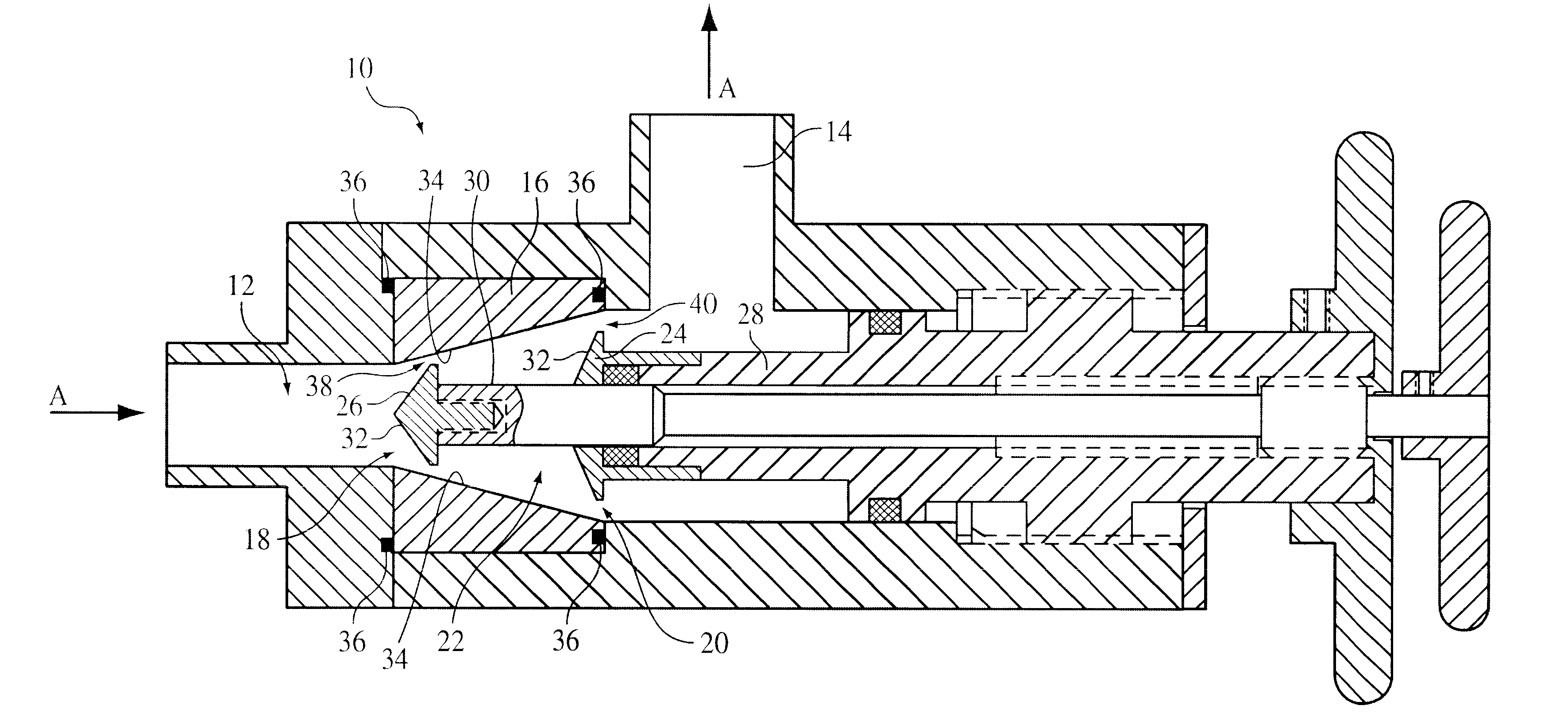
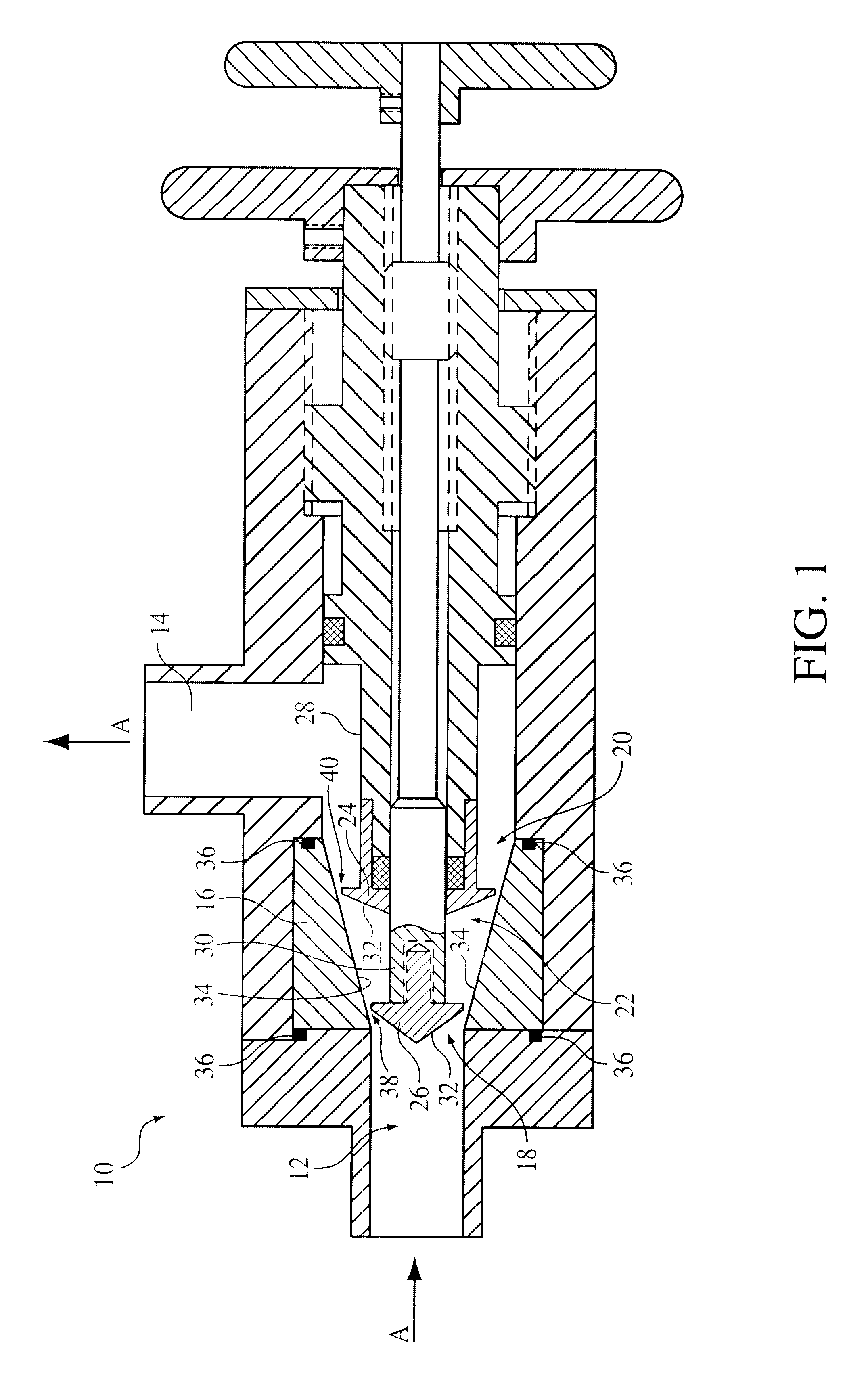
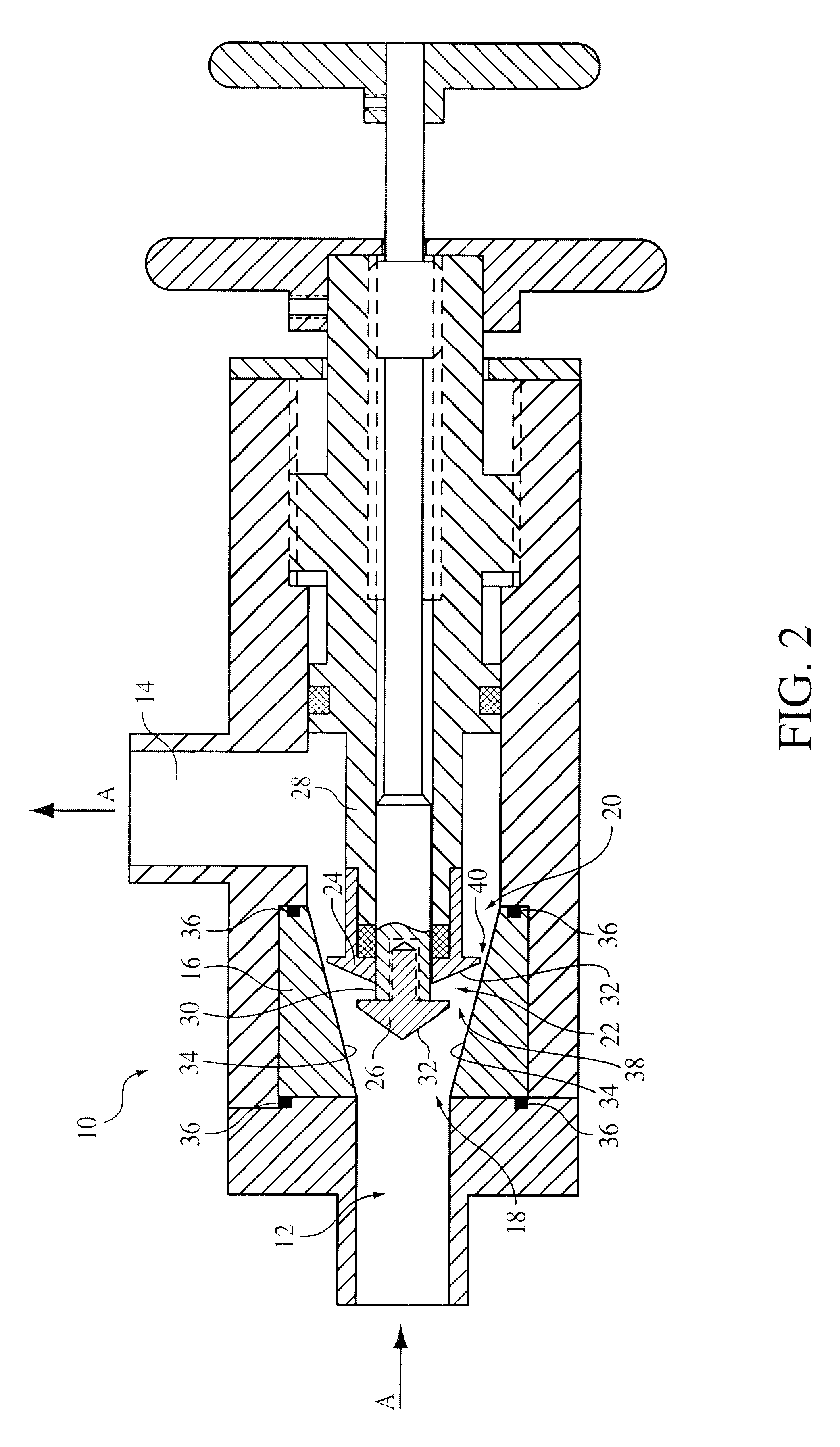
In accordance with this invention, and as shown in FIG. 1, a device 10 for creating hydrodynamic cavitation in fluids comprises an inlet opening 12 for accepting fluid and dispersants into the device 10; an outlet opening 14 for exiting the fluid and dispersants from the device 10; a flow-through chamber 16 intermediate the inlet opening 12 and the outlet opening 14 having an upstream opening portion 18 communicating with the inlet opening 12 and a downstream opening portion 20 communicating with the outlet opening 14, wherein the cross-sectional area of the downstream opening portion 20 of the flow-through chamber 16 is greater than the cross-sectional area of the upstream opening portion 18 of the flow-through chamber 16; and a cavitation generator 22 located within the flow-through chamber 16 for generating a hydrodynamic cavitation field downstream from the generator 22. Fluid flow in this device 10 is shown in the direction a arrow A in FIGS. 1 through 3.

For the sake of simplic...


PUM

PropertyMeasurementUnit
Flow rateaaaaaaaaaa
Diameteraaaaaaaaaa
Shapeaaaaaaaaaa

Abstract

This invention provides a device and method for creating hydrodynamic cavitation in fluids which includes a flow-through chamber intermediate an inlet opening and an outlet opening; the flow-through chamber having an upstream opening portion communicating with the inlet opening and a downstream opening portion communicating with the outlet opening; the cross-sectional area of the downstream opening portion being greater than the cross-sectional area of the upstream opening portion; and a cavitation generator located within the flow-through chamber for generating a hydrodynamic cavitation field downstream from the generator. This invention also provides for a device for creating hydrodynamic cavitation in fluids wherein the walls of the flow-through chamber are removable mounted within the device and are interchangeable and replaceable with replacement walls having various shapes and configurations, thereby enabling the flow-through chamber to assume various shapes and configurations to affect cavitation. This invention also provides for a device for a device for creating hydrodynamic cavitation in fluids wherein the baffle elements are removably mounted within the device and are interchangeable and replaceable with replacement baffles having various shapes and configurations thereby enabling variable effects on cavitation.

Description

The present invention relates to a device and method for creating hydrodynamic cavitation in fluids, and particularly, to a device and method for creating and controlling hydrodynamic cavitation in fluids wherein the position of structural components which create cavitation and the structural components themselves are easily variable.One of the most promising courses for further technological development in chemical, pharmaceutical, cosmetic, refining, food products, and many other areas relates to the production of emulsions and dispersions having the smallest possible particle sizes with the maximum size uniformity. Moreover, during the creation of new products and formulations, the challenge often involves the production of two, three, or more complex components in disperse systems containing particle sizes at the submicron level. Given the ever-increasing requirements placed on the quality of dispersing, traditional methods of dispersion that have been used for decades in techno...

Claims


Application Information

Patent Timeline
IPC IPC(8): B01F5/08B01F5/06B01F3/08B01F25/46
CPCB01F5/08B01F5/068B01F5/0665B01F3/0807B01F23/41B01F25/4413B01F25/4422B01F25/46
Inventor KOZYUK, OLEG V.
Owner ARISDYNE STSTEMS INC
Why Eureka
Try Eureka