Metal-face-seal rock bit

a technology of metal face and seals, applied in earth-moving drilling, cutting machines, construction, etc., can solve the problems of accelerating the abrasion wear of all seal components, deformation and/or slippage of elastomeric seal components,

Inactive Publication Date: 2003-02-04
BAKER HUGHES INC
View PDF23 Cites 43 Cited by
  • Summary
  • Abstract
  • Description
  • Claims
  • Application Information

AI Technical Summary

Problems solved by technology

When the solid matter in drilling fluid is carried into the seal gland, it adheres to gland and/or seal component surfaces and causes d

Method used


Image

  • Metal-face-seal rock bit
  • Metal-face-seal rock bit
  • Metal-face-seal rock bit

Examples


second embodiment

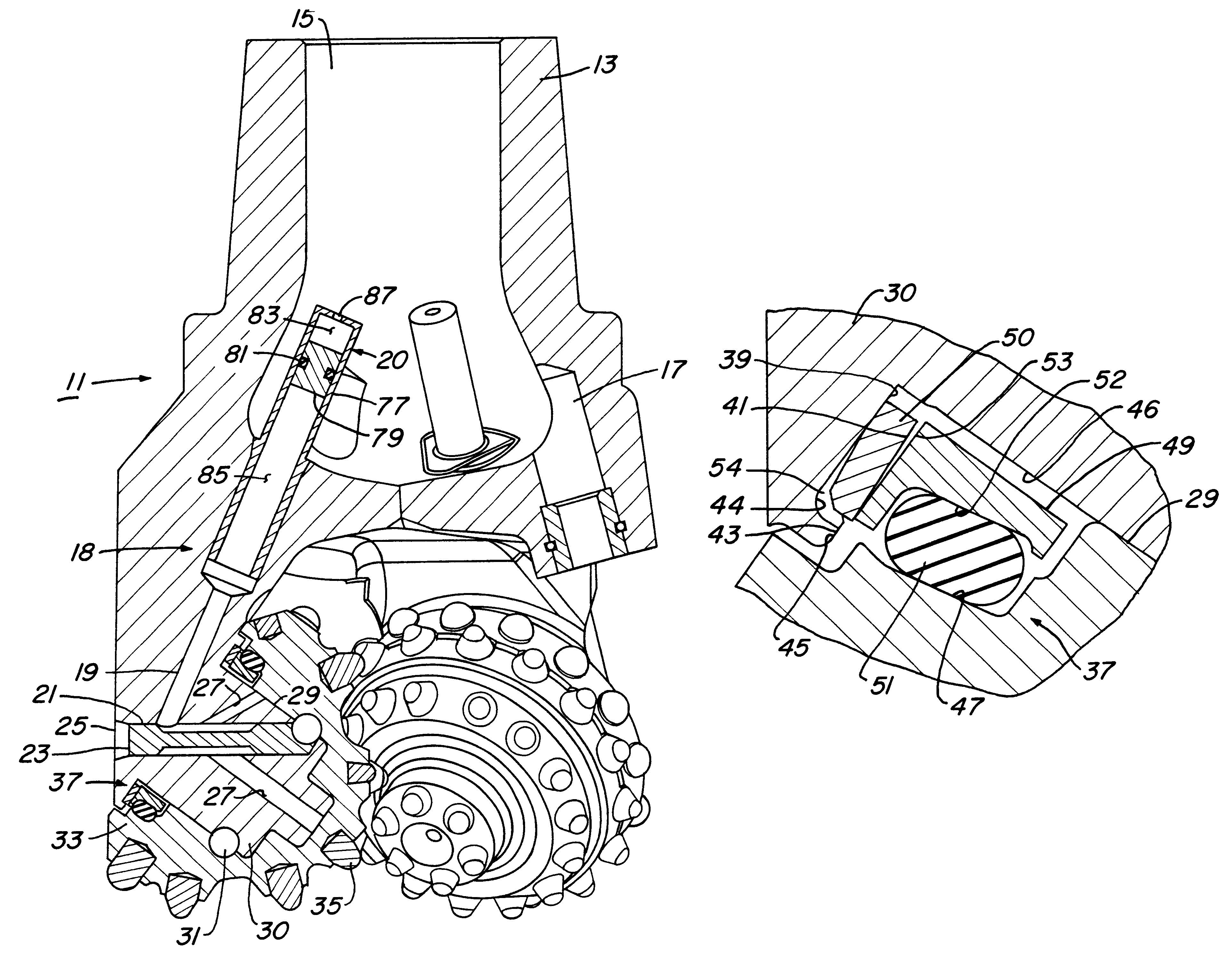
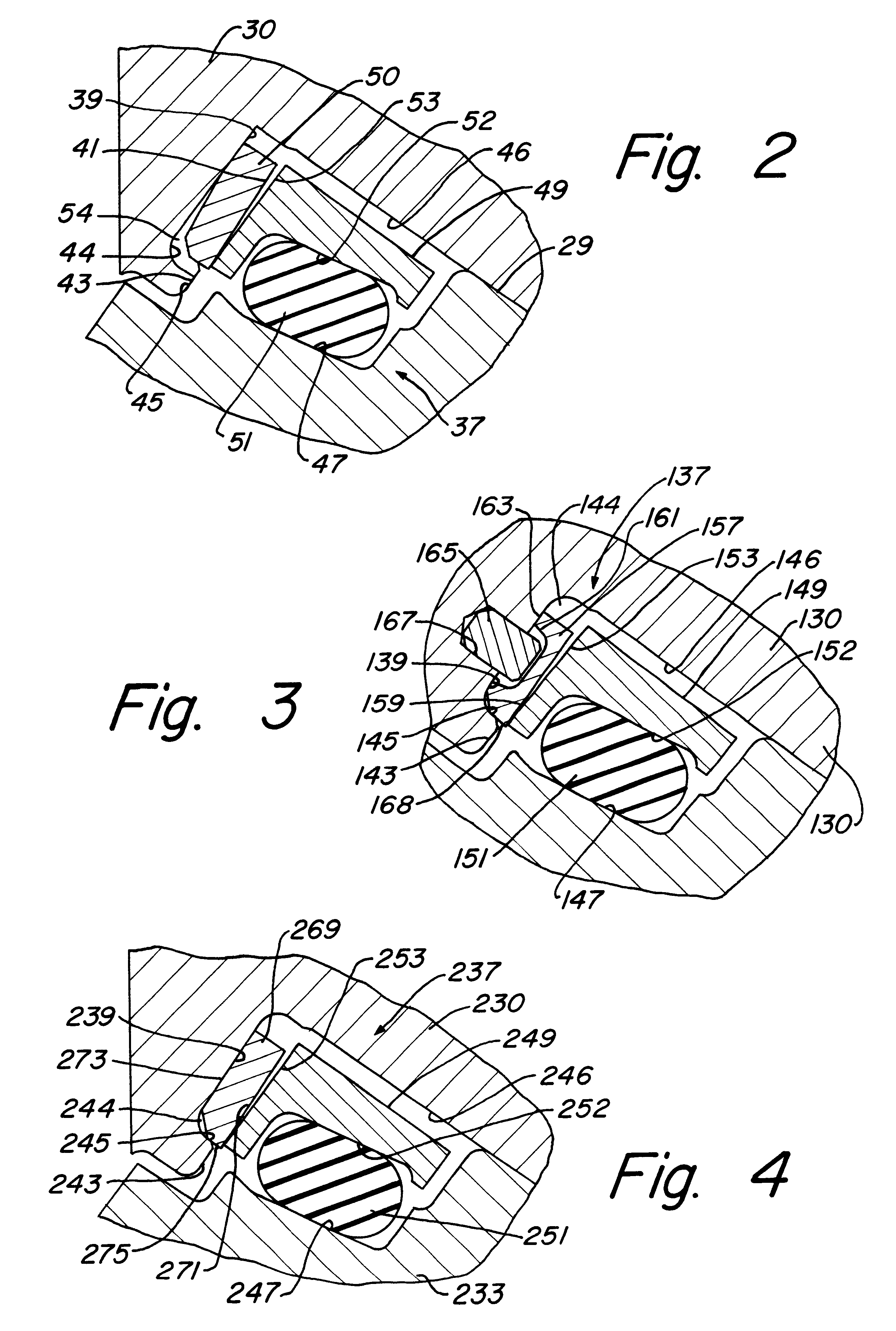
FIG. 3 shows seal assembly 37 (FIG. 1) Seal assembly 137 includes an o-ring 151 which sealingly engages surfaces 147 and 152 and energizes ring 149, as described above, for sealingly engaging rigid ring 157. Ring 157 has a sealing face 159 for engaging sealing face 153 of ring 149. Ring 157 has a plurality of recesses 161 in th lower surface 163 of ring 157 for receiving a plurality of dowels 165. Dowels 165 are insert ed into holes 167 in cylindrical surface 139. Surface 163 of ring 157 is bonded to surface 139 and recesses 161 are bonded to dowels 165 for preventing rotation of ring 157 within recess 144. Outer surface 168 of ring 157 sealingly engages lip 145. Ring 157 extends slightly above surface 143 when installed in recess 144.

third embodiment

seal assembly 37 (FIG. 1) is shown in FIG. 4. Seal assembly 237 includes a rigid ring 269 having a surface 271 that provides the counterface or sealingly engaging surface 253 of ring 249. The lower surface 273 of ring 269 is flat and continuous. Surface 273 is bonded to surface 239 of recess 244, and outer surface 275 sealingly en ages lip 245. When installed, ring 269 extends slightly above surface 243.

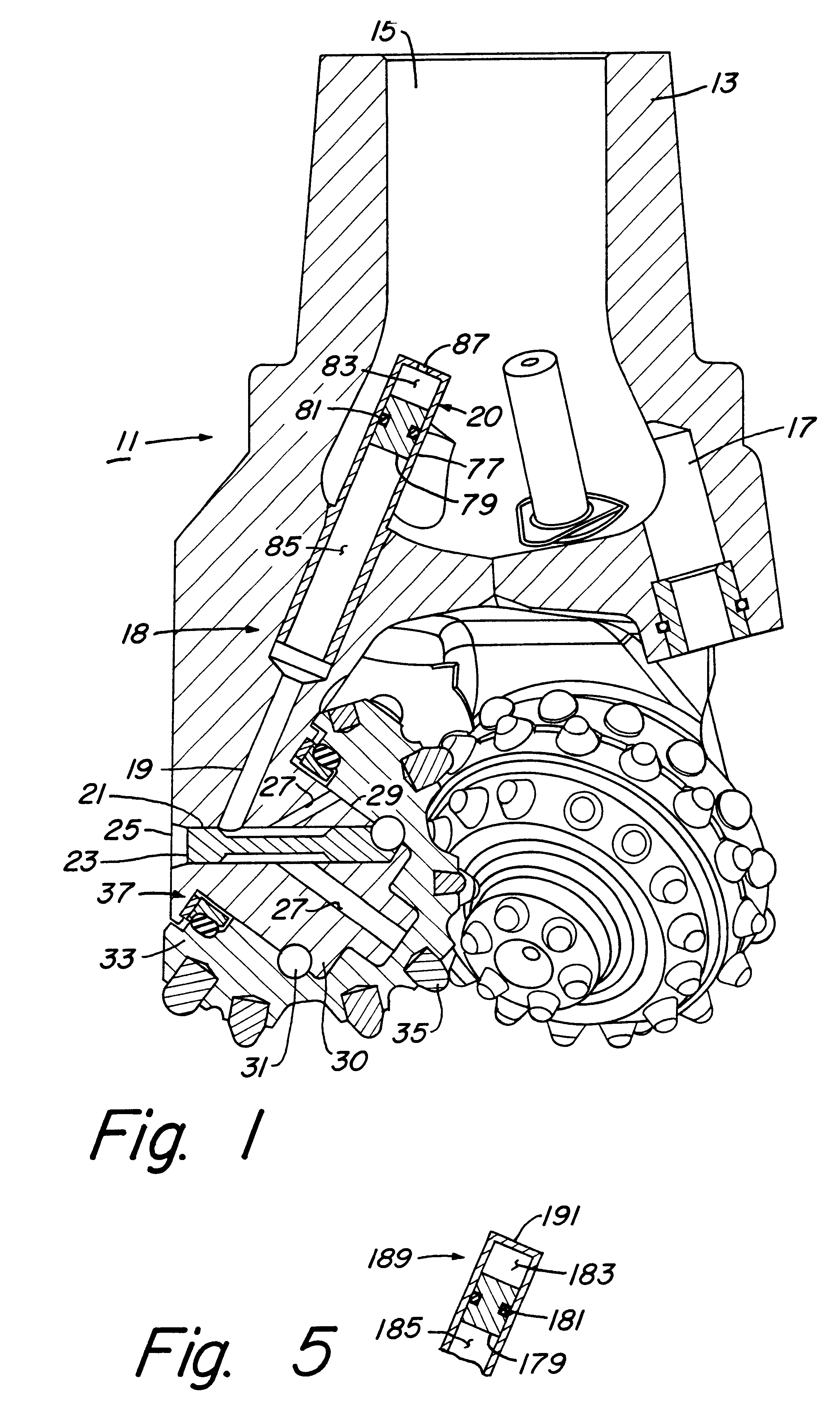
FIG. 5 shows the upper end of a second embodiment of a lubricant compensator. Compensator 189 has a body 191 having a closed upper end. A piston 179 is movably carried within body 191 and has an o-ring seal 181 for sealingly engaging the inner surface of body 191. Piston 179 and seal 181 divide the interior of body 191 into an upper volume 183 and lower volume 185. Lubricant is pumped into volume 185 to force piston 179 upward in body 191 As piston 179 is moved upward, the size of volume 183 decreases, and air contained in volume 183 by seal 181 is compressed. The compressed air caus...


PUM


Abstract

A bit is provided having at least one leg extending downwardly and inwardly from the bit body. A cutter cone is rotatably mounted on a shaft extending inwardly from the lower portion of each leg. The annular space defined by the base of the shaft and the inner surface at the base of the cone forms a seal gland. An elastomeric o-ring sealingly engages an inner surface of the cone and a first rigid ring which rotates with the o-ring and cone. The o-ring energizes the first rigid ring for sealingly engaging a second rigid ring mounted to the leg of the bit near the base of the shaft. The second rigid ring is secured to and seals against a surface at the base of the shaft and is held stationary relative to the surface. A lubricant passage for lubricating the seal is pressurized by the drilling fluid pressure in the center of the bit body.

Description

1. Field of the InventionThe present invention relates in general to earth-boring bits, particularly to those having rotatable cutters in which seal assemblies retain lubricant within the bearing areas.2. Background InformationOne of the most successful seal means used in earth-boring bits of the type having rotatable cutters is the O-ring seal disclosed in commonly assigned U.S. Pat. No. 3,397,928, to Galle. The o-ring seal successfully confines lubricant to the bearing area while excluding detritus for long periods of time before failure.A more recent seal development is the rigid or metal face seal. In the rigid face seal type, the seal interface is between one or two rigid, usually steel, seal rings. One or two elastomer o-rings serve to energize or urge the seal faces of the rigid ring or rings in contact with each other. The rigid face seal has proved to be as successful as the o-ring seal and provides an improved ability to accommodate pressure fluctuations in the bit lubrica...

Claims


Application Information

Patent Timeline
IPC IPC(8): E21B10/24E21B10/08E21B10/22E21B10/25
CPCE21B10/25E21B10/24
Inventor PETERSON, GREGORY W.WALK, HOWARD J.
Owner BAKER HUGHES INC
Why Eureka
Try Eureka