Wheel rim locking device for tire removal machines

a locking device and tire removal technology, applied in the field of self-centering devices, can solve the problems of extended operating time and drawback of insecure wheel locking against rotation

Inactive Publication Date: 2003-02-11
NEXION SPA
View PDF8 Cites 21 Cited by
  • Summary
  • Abstract
  • Description
  • Claims
  • Application Information

AI Technical Summary

Benefits of technology

The invention attains said object by providing a device for locking the wheel rim at the hub, comprising means for rotating the wheel even if considerable tangential resistance forces are present.

Problems solved by technology

This both demands physical force from the operator and results in an extension of the operating time.
On the other hand, those systems which lock the wheel at the hub, and which allow access to both sides of the wheel at the same time, present the drawback of insecure wheel locking against rotation, which is often precarious.

Method used


Image

  • Wheel rim locking device for tire removal machines
  • Wheel rim locking device for tire removal machines
  • Wheel rim locking device for tire removal machines

Examples


Embodiment Construction

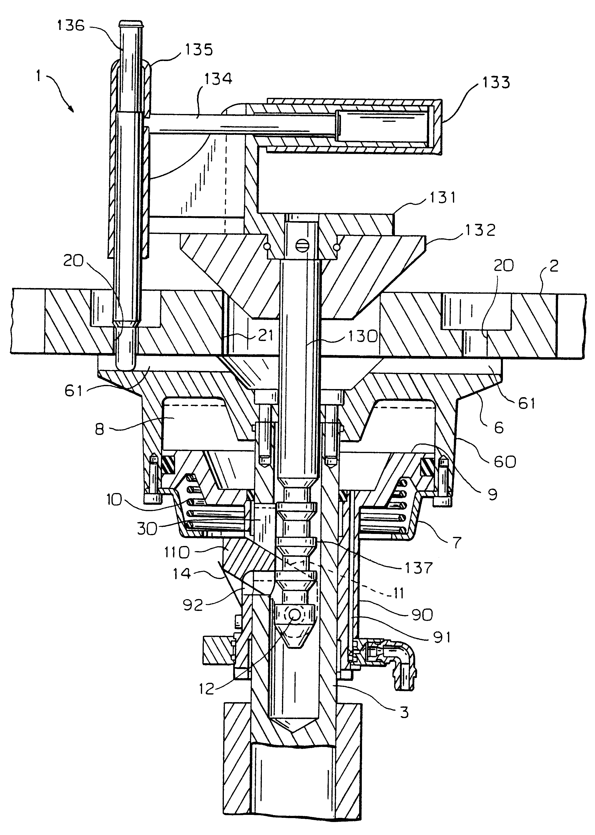
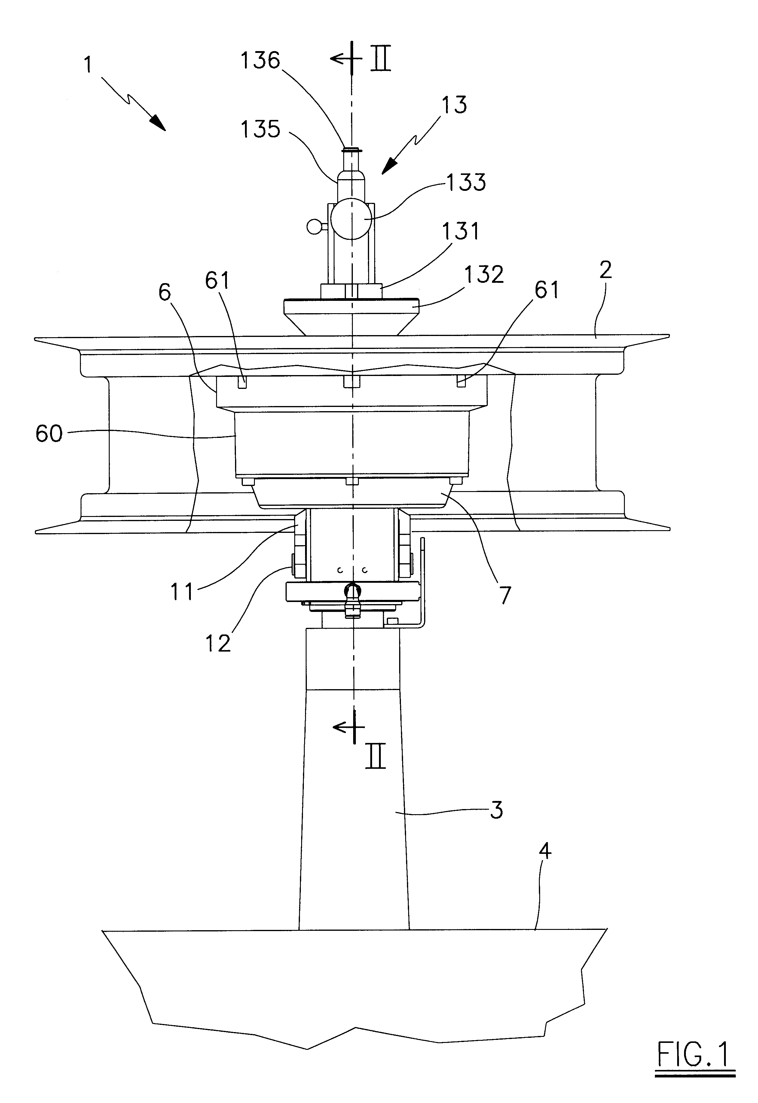
The aforestated figures show the device 1 for supporting and locking the wheel rim 2.

The device comprises a shaft 3 rotated by known means, not shown, and which projects from the base 4 of the tyre removal machine, also not shown.

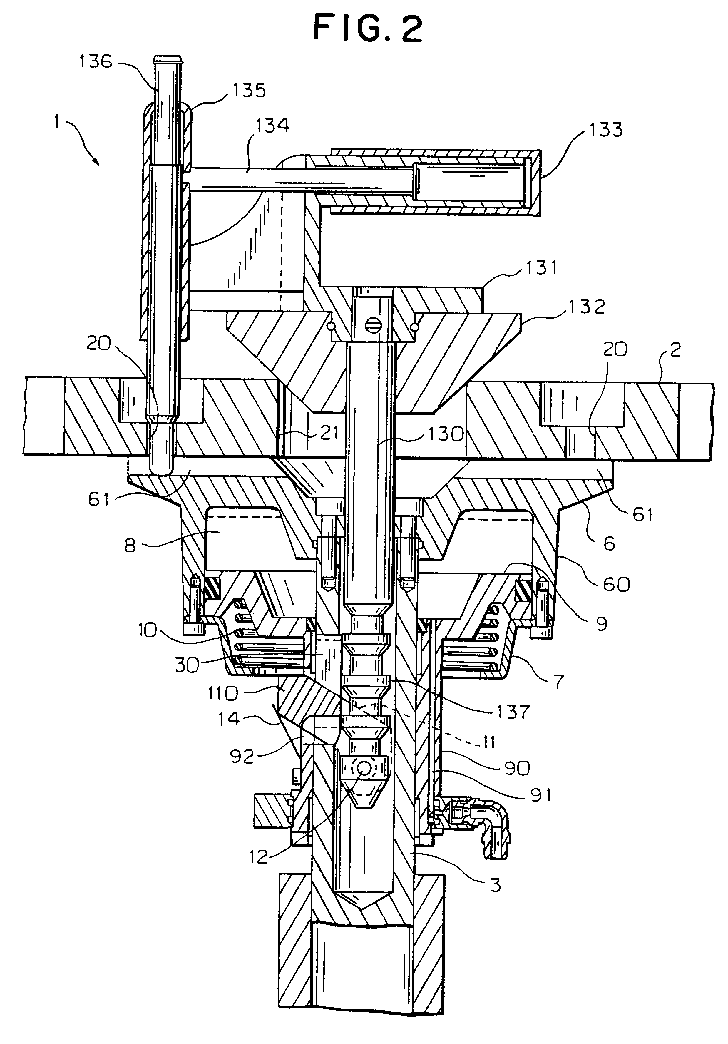
With reference to FIG. 2, the shaft 3 supports at its upper end a circular plate 6, on which the wheel rim 2 is rested.

The plate 6 is provided with an axial hole and six equidistant radial grooves 61.

The plate 6 is also provided with an annular descending lower skirt 60, to the free end of which there is fixed a cover 7 which, together with said skirt 60, defines a chamber 8.

Within the chamber 8 there sealedly slides an annular piston 9, provided with a rod 90 sealedly mounted about the shaft 3.

A part of the shaft 3 is axially hollow, the cavity being of hexagonal cross-section.

Within the wall of the hollow rod 90 there is present a conduit 91 through which a pressurized fluid is fed above the piston 9.

Between said piston 9 and said cover 7 there is interpo...


PUM


Abstract

A wheel rim locking device for tire removal machines, comprising, for supporting the wheel rim, an upper plate provided with an axial hole and supported at the top of a hollow vertical rotary shaft, conical means to be inserted axially into said hole and into the cavity of said shaft to lock the wheel rim in a centered position, means driving said conical means towards the wheel rim and axially locking them, and means for rotatably locking said hollow shaft relative to said wheel rim.

Description

1. Technical Field of the InventionThis invention relates to a self-centering device for locking the wheel rim for the purpose of mounting or removing its tyre.2. Prior ArtTo lock the wheel rim in the working position, tyre removal machines are currently provided with suitable devices, known as self-centering devices, which generally comprise a circular plate provided with a series of radial grooves within which sliding blocks having locking heads (fasteners) which lock the wheel rim in the working position are made to slide. The locking heads, generally four in number, are equidistant about a circumference, and are of the double acting radial sliding type, in order to be able to grip the wheel rim both from the outside and from the inside.The circular plate is rotated about itself by a coaxial shaft driven by a suitable motor unit.The sliding blocks are caused to slide within the grooves by a double-acting cylinder-piston unit positioned coaxial to the shaft and acting on levers co...

Claims


Application Information

Patent Timeline
Patent Type & Authority Patents(United States)
IPC IPC(8): B60C25/132B60C25/00B60C25/05B60B30/06
CPCB60C25/0545B60C25/0536B60C25/132
Inventor CORGHI, REMO
Owner NEXION SPA
Why Eureka
Try Eureka