Cord clip

a cord clip and clip technology, applied in the field of cord clips, can solve the problems of inadvertent simultaneous detachment of the cord, high part cost and assembly cost of assembling these parts,

Inactive Publication Date: 2003-03-04
HOSIDEN CORP
View PDF9 Cites 51 Cited by
  • Summary
  • Abstract
  • Description
  • Claims
  • Application Information

AI Technical Summary

Benefits of technology

The present invention has been made in view of the problems described above and its primary object is to provide improved cord clip comprising a clipping portion and a cord holding portion which portions are formed as one integral component and which portions provide respective effective forces independently of each other.
With the cord clip having the above-described construction, as the first annular portion constituting the clipping portion having a clamping portion for clamping an object such as a clothes and the second annular portion constituting the cord holding portion for holding the cord are formed integrally in a single elastic member, the number of parts required may be reduced to the minimum (only one). As a result, the parts costs and the assembly costs may be reduced. Further, because the elastic resilient force applied to clamp the object, e.g. a clothes and the elastic resilient force applied to hod the cord are independent of each other, it is possible to avoid mutual interference between these forces. Hence, when the clamping of the clothes at the clipping portion is released, there will occur no inadvertent release of the cord at the cord holding portion.

Problems solved by technology

The above-described conventional cord clip 10 has many parts, so that it presents the problem of high part costs and high assembly costs for assembling these parts.
However, such construction has proved unsatisfactory since when the alligator clip 15 is opened to be detached from the clothes, this may result in inadvertent simultaneous detachment of the cord.

Method used


Image

  • Cord clip
  • Cord clip
  • Cord clip

Examples


Embodiment Construction

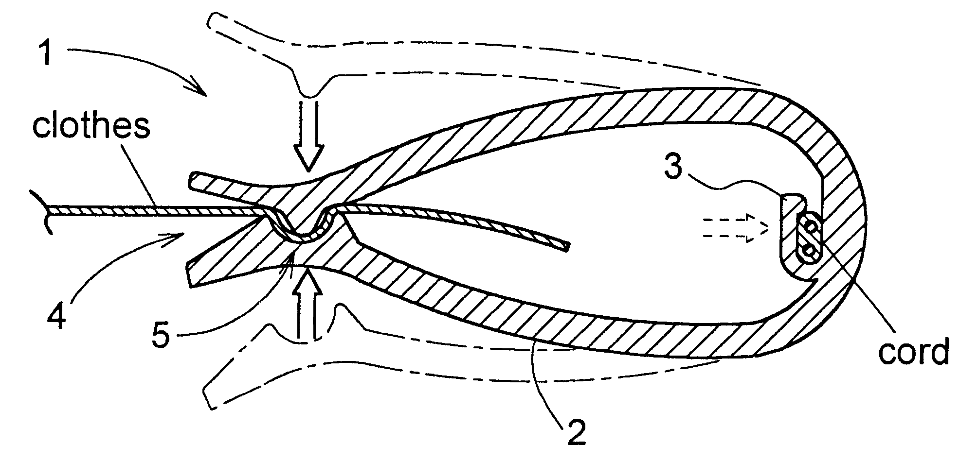
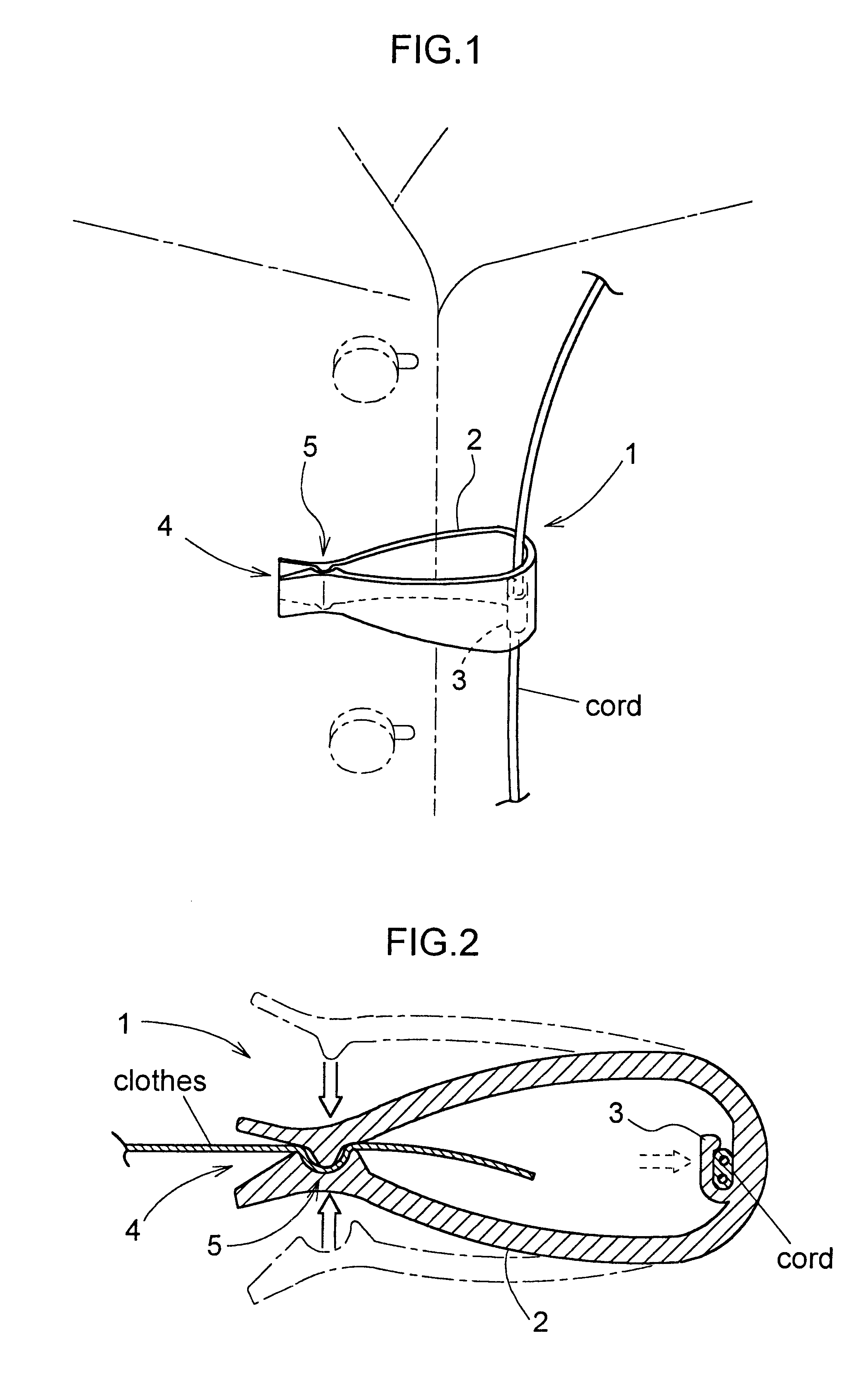
Preferred embodiments of a cord clip relating to the present invention will be described below with reference to the accompanying drawings.

A cord clip 1 shown in FIG. 1 and FIG. 2 includes a clipping portion 2 formed by a first annular portion which has a discontinuity at a part thereof and has elasticity and a cord holding portion 3 formed by a second annular potion which has a discontinuity at a part thereof and has elasticity. The clipping portion 2 is capable of clamping an object such as a clothes at a clamping portion 5 thereof provided by a narrow gap formed by the discontinuity of the first annular portion by means of an elastic resilient force from the first annular portion. On the other hand, the cord holding portion 3 is capable of holding a cord therein by means of an elastic resilient force from the second annular portion, which elastic resilient force is independent of the elastic resilient force of the first annular portion. Further, the clipping portion 2 formed by t...


PUM


Abstract

A cord clip for fastening a cord attached to e.g. an earphone to an object such as a clothes is disclosed. The cord clip includes a clipping portion for clamping the object and a cord holding portion for holding the cord. The clipping portion is formed by a first annular portion having a discontinuity at a part thereof. The clipping portion is capable of clamping the object at a clamping portion thereof provided by a narrow gap formed by the discontinuity of the first annular portion by means of an elastic resilient force of the first annular portion. The cord holding portion is formed by a second annular portion having a discontinuity at a part thereof. The cord holding portion is capable of holding the cord therein by means of an elastic resilient force of the second annular portion. This elastic resilient force of the second annular portion is independent of that of the first annular portion. The first annular portion and the second annular portion are formed integrally in a single member.

Description

1. Field of the InventionThe present invention relates to a cord clip for fastening a cord attached to e.g. an earphone to a clothes. More particularly, the invention relates to such cord clip having a clipping portion capable of clamping an object at a clamping portion thereof and a cord holding portion capable of holding the cord.2. Description of the Related ArtA conventional cord clip will be described with reference to FIG. 3. As shown, a cord clip 10 includes an alligator clip 15 consisting essentially of a spring 11, a shaft 12 and a pair of clipping portions 13, 14 and a cord holding portion 16. The alligator clip 15 and the cord holding portion 16 are connected with each other, so that in use, the cord holding portion is used for securely holding the cord of an earphone or the like and the alligator clip is used for clamping a clothes, thereby to secure the cord to the clothes.The above-described conventional cord clip 10 has many parts, so that it presents the problem of h...

Claims


Application Information

Patent Timeline
Patent Type & Authority Patents(United States)
IPC IPC(8): A45F5/02A45F5/00F16G11/00H01R4/48F16B2/22H04R1/10
CPCA45F5/02A45F2200/0508Y10T24/44769Y10T24/3453Y10T24/44778Y10T24/44923Y10T24/44752Y10T24/1408H01R4/48
Inventor NASU, KOJIFUJIWARA, SATORU
Owner HOSIDEN CORP
Why Eureka
Try Eureka