Method and apparatus for cleaning fluid ejection cartridge and maintenance station

a technology of fluid ejection and maintenance station, which is applied in the direction of coatings, pretreated surfaces, printing, etc., can solve the problems of inability to meet the intended use of the intended use, the quality of the printed product or printed image will be decreased, and the inability to meet the intended us

Inactive Publication Date: 2003-03-11
XEROX CORP
View PDF3 Cites 18 Cited by
  • Summary
  • Abstract
  • Description
  • Claims
  • Application Information

AI Technical Summary

Benefits of technology

The systems and methods according to this invention provide a simple, easy-to-use cleaning technique for fluid ejection systems, including ink jet printers, which does not involve a separate toner concentration holding station, a diluent holding station with separate diluent supply lines, a toner sump, or elaborate sensing equipment.

Problems solved by technology

If the user of a fluid ejection system, such as an ink jet printer or plotter, changes an ink color or type of ink being used in the fluid ejection system, such as, for example, a change from certain subtractive primary inks to pantone color or photographic color inks, if the new ink is incompatible with the old ink, the quality of the printed product or printed image will be decreased, often to the point of being unfit for its intended use.
Unfortunately, this is not always possible.

Method used


Image

  • Method and apparatus for cleaning fluid ejection cartridge and maintenance station
  • Method and apparatus for cleaning fluid ejection cartridge and maintenance station
  • Method and apparatus for cleaning fluid ejection cartridge and maintenance station

Examples


Embodiment Construction

The following detailed description of various exemplary embodiments of the fluid ejection systems according to this invention are in part directed to one specific type of fluid ejection system, an ink jet fluid printer, for sake of clarity and familiarity. However, it should be appreciated that the principles of this invention, as outlined and / or discussed below, can be equally applied to any known or later-developed fluid ejection systems, beyond the ink jet fluid printer specifically discussed herein.

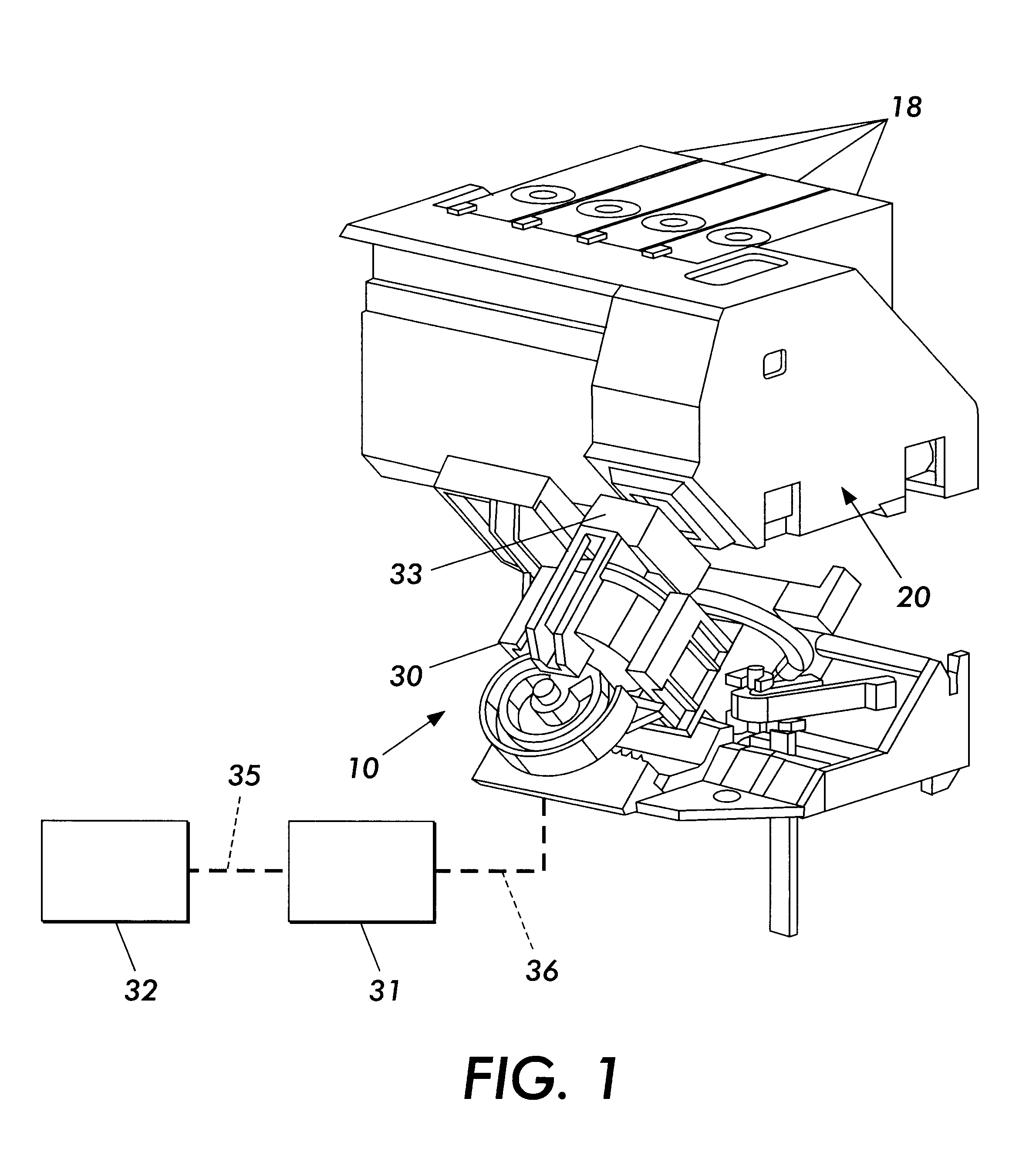
FIG. 1 shows one exemplary embodiment of an ink jet printer 10 that uses one or more ink supply containers 18 connected to the fluid ejector 20. The ink jet printer 10 also includes a capping / maintenance station 30 that includes a cap chamber 33 usable to cap fluid ejector 20. At the end of a fluid ejection operation, the scanning carriage (not shown) is parked in a maintenance position confronting the maintenance station 30. The maintenance station includes a chamber 33 and an associ...


PUM


Abstract

An improved method of upgrading an image transfer engine such as, for example, an ink jet fluid printer or plotter using liquid ink, or a xerographic device using a liquid toner is disclosed. A removable ink flush tank / cartridge containing an ink cleaner is substituted for a removable ink tank, permitting complete cleaning of ink from the ink fluid flow paths in the engine. This results in less contamination of new inks with previously used inks in the engine.

Description

1. Field of InventionThis invention relates to fluid ejection systems having fluid ejection heads and replaceable fluid supply cartridges.2. Description of Related ArtFluid ejection systems, such as, for example, ink jet fluid printers and plotters, have a fluid ejection head with a fluid supply, either integral with the fluid ejection head, or connected to the fluid ejection head. A fluid ejection head contains a plurality of fluid channels that carry fluid from the fluid supply, such as, for example, a fluid supply cartridge, to respective fluid ejecting nozzles. A maintenance / capping station is often provided in such fluid ejection systems. At the end of an ejection operation, the fluid supply cartridge and fluid ejection head face are placed opposite the maintenance / capping station. The maintenance / capping station includes a capping chamber and an associated suction pump communicating through a waste tank and conduit lines. The capping chamber is movable into and away from the f...

Claims


Application Information

Patent Timeline
Patent Type & Authority Patents(United States)
IPC IPC(8): B41J2/17B41J2/165B05D1/26B41J2/175B05D3/10
CPCB41J2/1707B41J2/16552
Inventor PREMNATH, KARAI P.TRENCHARD, THOMAS J.CARREIRA, LEONARD M.CURRAN, JR., DONALD P.
Owner XEROX CORP
Why Eureka
Try Eureka