Separator mill

a separation mill and separator technology, applied in the field of separation mills, can solve the problems of high risk of residual small amounts of previous products in the machine, time-consuming and complicated cleaning of conventional separation mills,

Inactive Publication Date: 2003-04-08
HOSOKAWA ALPINE AG
View PDF9 Cites 28 Cited by
  • Summary
  • Abstract
  • Description
  • Claims
  • Application Information

AI Technical Summary

Problems solved by technology

Cleaning of conventional separating mills is complicated and time consuming.
In particular, there is a high risk that there will still be small residual amounts of the previous product in the machine even after cleaning.

Method used


Image

  • Separator mill
  • Separator mill
  • Separator mill

Examples


Embodiment Construction

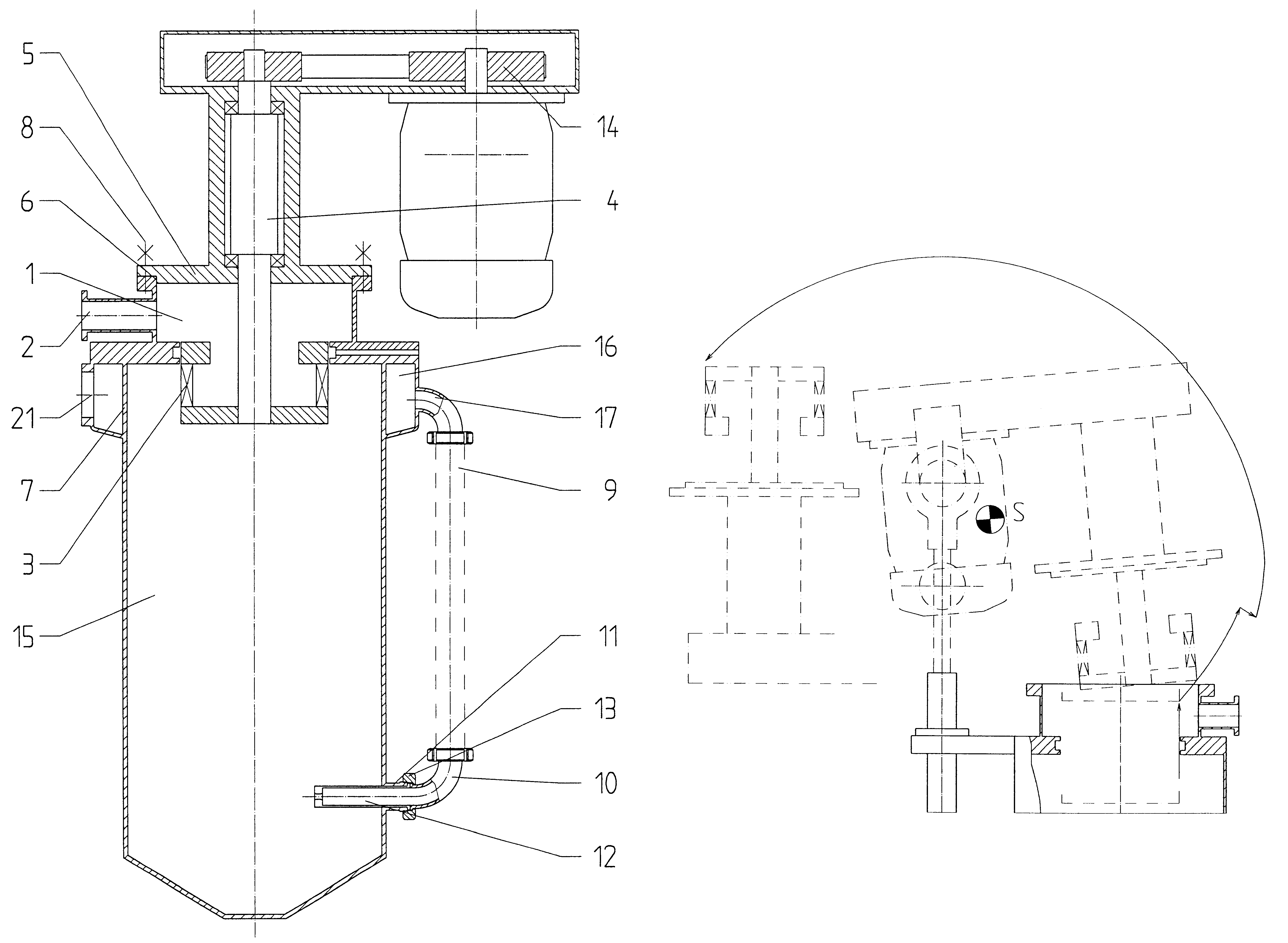
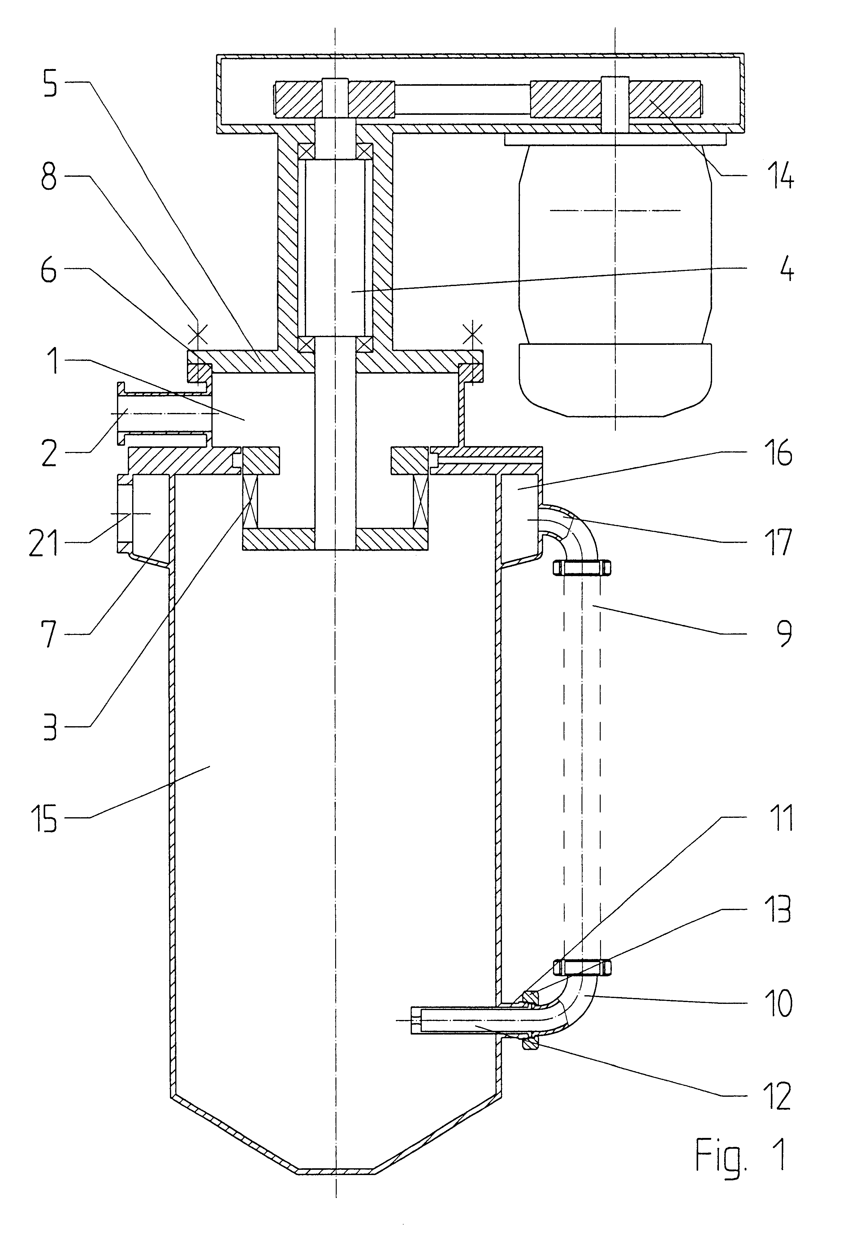
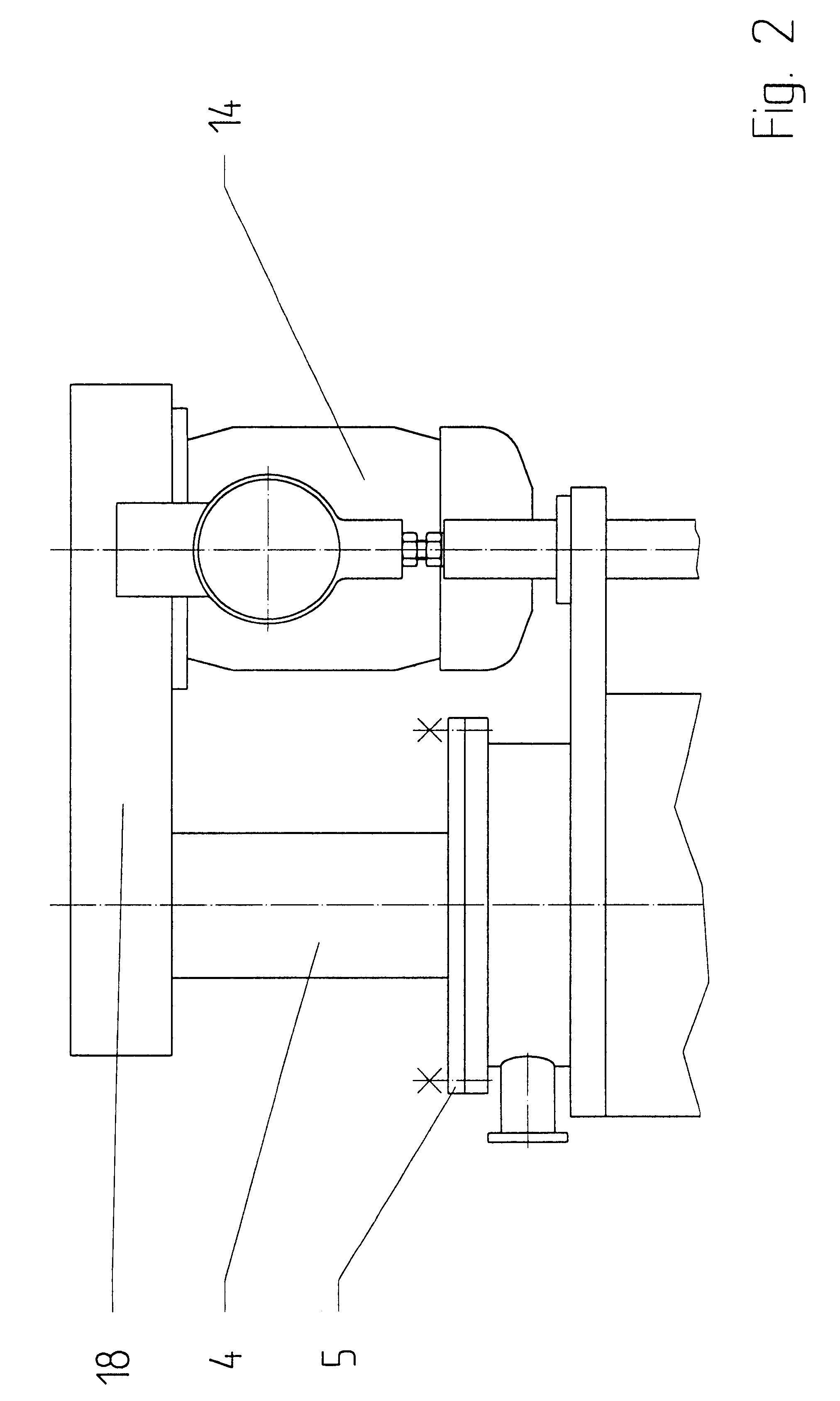
As explained above, the fluidized-bed opposed jet mill according to the invention provides a separator arrangement that forms one component from the mounting device and the actuator and that is attached to the grinding container in a detachable manner. In this arrangement, the component can move relative to the grinding container by means of kinematic devices, in such a way that the separator wheel can be removed from the grinding container upwards through the discharge opening for the finely ground material. The discharge opening for the finely ground material remains attached to the grinding container.

Thus, the grinding container is not disassembled and made accessible in a plane between the lower part containing the grinding area, and the upper part containing the separator, but instead the separating plane is located within the area of the separator. This not only has the advantage that the grinding area is fully accessible, but also that the separator becomes accessible from th...


PUM


Abstract

Fluidized-bed opposed jet mills, configured as separator mills, and provided with easy accessibility so that the interior space can be easily cleaned with little effort. The separator wheel is formed together with the bearing unit and the actuator unit as one component, which is detachably attached to the grinding container and can be moved relative to the grinding container by kinematic devices in such a manner that the separator wheel can be removed from the grinding container upward through the discharge outlet for finely ground material, while the discharge device for the finely ground material remains connected to the grinding container. In this manner, the separator mill can be easily assembled and disassembled by the user and the separator mill becomes easily accessible for thorough cleaning. This is particularly advantageous when the material to be ground is changed frequently, as is the case in the pharmaceutical and chemical fields.

Description

1. Field of the InventionThe invention relates to a separator mill, and more particularly, fluidized-bed opposed jet mills configured as separator mills, and to the arrangement of components therefore.2. Description of the Prior ArtFluidized-bed opposed jet mills generally consist of a cylindrical grinding container set on a vertical axis, wherein gas jets are provided in the lower part of the grinding container. These gas jets are directed in opposite directions in such a manner that the material to be ground in the grinding container is sucked into the airflow and accelerated by the airflow so that the material is crushed on impact as the particles of the material to be ground collide with each other.In order to remove already-ground fine material from the mill, while leaving material that has not yet been sufficiently ground in the mill, the upper part of the grinding container contains a separating device. The separating device is usually embodied as a separator that uses centri...

Claims


Application Information

Patent Timeline
Patent Type & Authority Patents(United States)
IPC IPC(8): B02C19/06B02C23/00B02C23/16B02C23/30
CPCB02C23/16B02C19/068
Inventor KONETZKA, GEORGEDER, HERMANN
Owner HOSOKAWA ALPINE AG
Why Eureka
Try Eureka