Bag separator and dispenser

a bag separator and bag dispenser technology, applied in the field of bags and dispensers, can solve the problems of preventing the core from easily falling down, unable to find or peel the bag from the bag roll, and unable to be easily removed by fingers

Inactive Publication Date: 2003-05-13
CRYOVAC INC
View PDF27 Cites 41 Cited by
  • Summary
  • Abstract
  • Description
  • Claims
  • Application Information

AI Technical Summary

Problems solved by technology

Sometimes consumers will tear or stretch the bags when trying to separate them or attempt to simply jerk the bag from the roll causing it to unravel.
Additionally, after a bag has been taken from the roll, the next bag may lie flat on the surface of the roll, making it very difficult to find or peel from the roll.
Moreover, removing bags from a roll of bags is a two-handed task.
However, the tension provided by the fingers deters the core from easily descending through the channels as the roll gets smaller.
A further problem with existing bag dispensers is that ink transf

Method used


Image

  • Bag separator and dispenser
  • Bag separator and dispenser
  • Bag separator and dispenser

Examples


Embodiment Construction

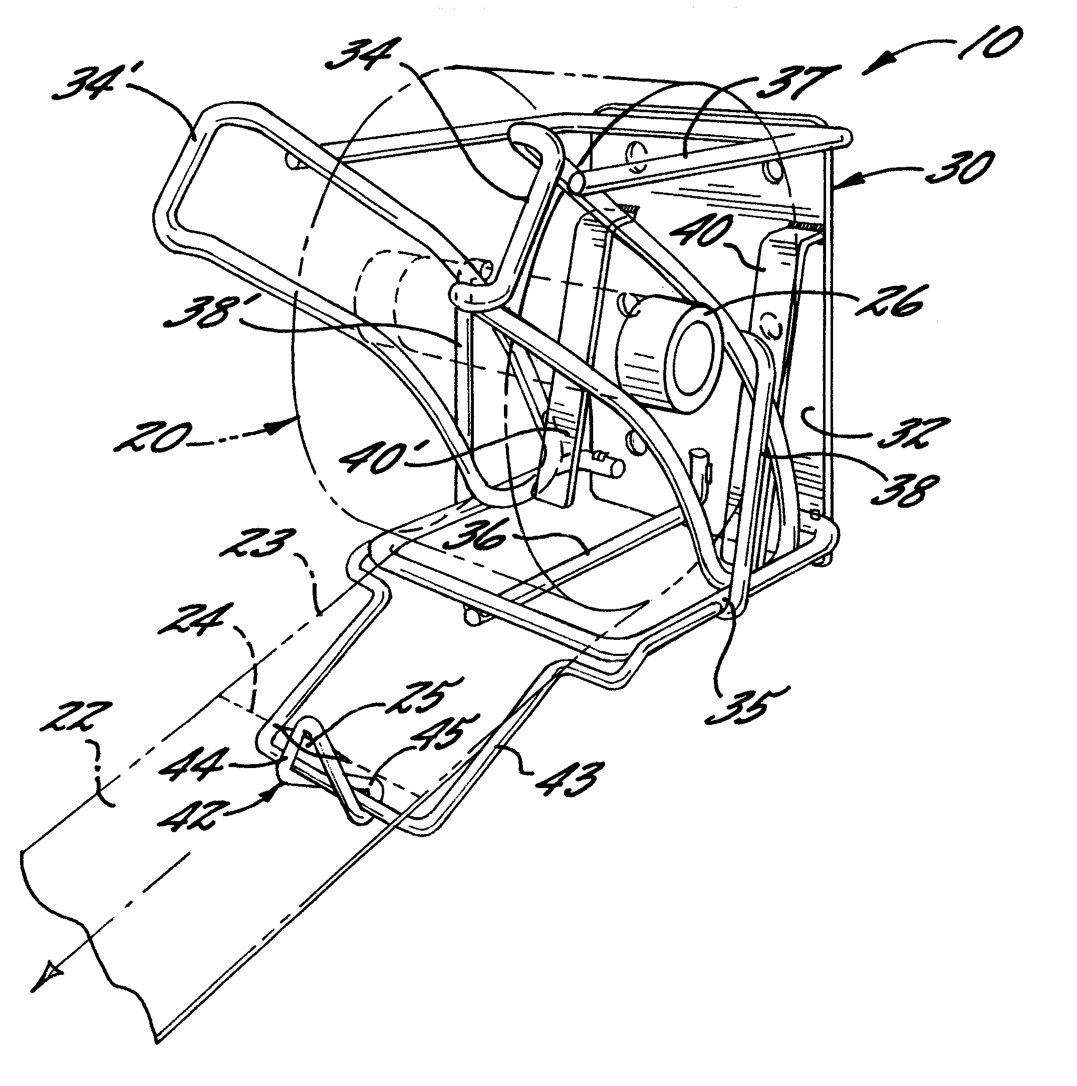
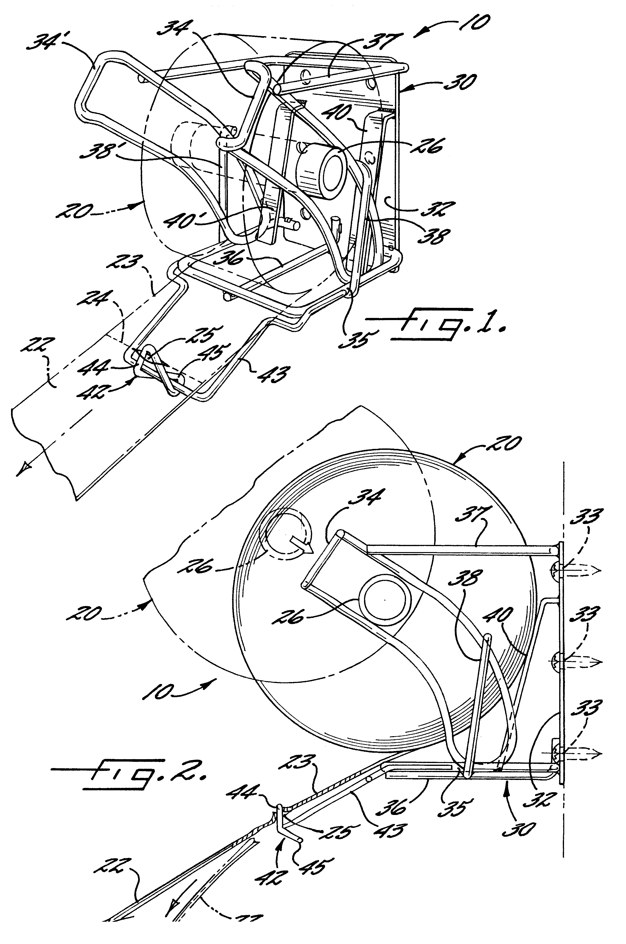
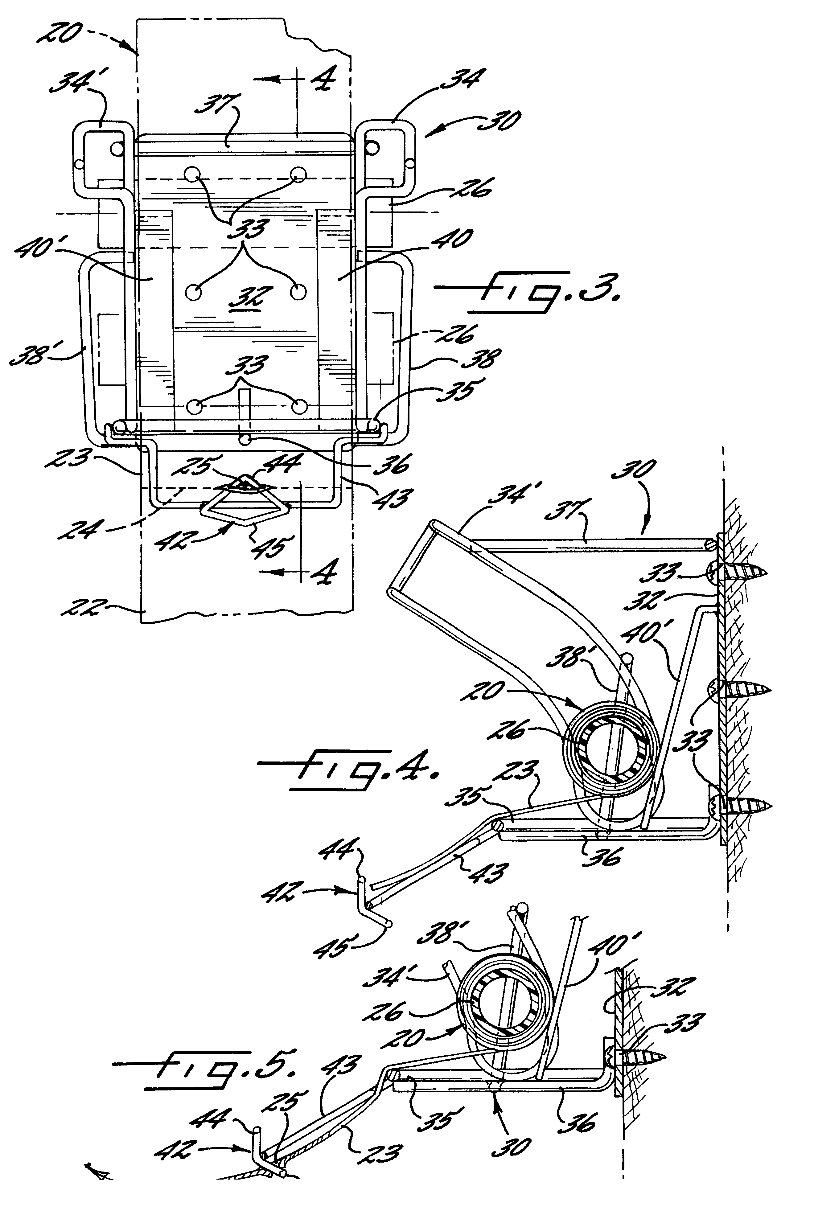
Referring now more specifically to the drawings, there is shown in FIG. 1 the bag dispensing system 10 embodying the features of the present invention. As illustrated, the bag dispensing system 10 includes a roll of plastic bags 20 and a dispenser 30. The roll of plastic bags 20 includes the end of a first bag 22 connected to the top of a next bag 23 and separated by a perforated tear line 24 including a slot 25 located in a predetermined position within the perforated tear line 24, preferably at or near the midpoint between the sides of the bag. The bags are rolled onto a core 26 to form a roll. The bag in the open position, i.e., when in use, may vary in width but is preferably about 12 inches. The bag is folded to a width of about 3 to about 4 inches when rolled onto the core 26. The slot 25 extends through each of the folds.

Bag dispenser 30 includes a support member 32, a pair of arcuate guide channels 34, 34', each having outer bar members 38, 38', a tensioning member, brake 40...


PUM


Abstract

A bag dispenser, for separating and dispensing plastic bags from a roll of bags where one end is attached to the top of the next bag by perforation lines with a slot therebetween. The bags are dispensed from a device comprising a wire frame formed into arcuate channels to support the core that the series of bags are rolled onto. The dispenser includes a second tensioning member attached to a support member and disposed at an angle thereto to provide tension to the edges of the roll of bags as the core passes through the channel passageway as bags are removed from the roll. Spaced apart from the support is a symmetric separating tongue. The tongue will engage the slot regardless of whether the bags are drawn over or under the tongue. As the user pulls on the bags, a tension is created by the brake and the user to deflect the tongue which remains deflected until the tongue engages the slot. Thus, when the separator engages the slot, the tongue recoils through its normal position to facilitate the separation of the two bags. The dispenser may also include core retaining members located at the closed end of the arcuate channels to keep the core of smaller rolls from popping out and to retard rotation of the core.

Description

1. Field of the InventionThe present invention relates generally to devices for dispensing bags. More specifically, the present invention relates to plastic bag dispensers where each bag is separated from a roll of bags.2. Description of the Prior ArtIn supermarkets and other types of food markets, fruits, vegetables, and other produce are displayed in bulk, on tables or in open coolers. Plastic bags are provided for consumers who want them for their produce selections. The most common way to dispense these produce bags is on cylindrical rolls mounted horizontally or vertically. The top of each bag is attached to the bottom of the next bag. Each bag may be separated from the next along a perforated line that defines the end of one bag and the start of the next bag. By grabbing a bag with one hand and the next bag with the other hand, and then pulling, the consumer can separate the two bags along the perforation line. Sometimes consumers will tear or stretch the bags when trying to s...

Claims


Application Information

Patent Timeline
IPC IPC(8): A47F13/08A47F13/00B65D33/00B65H35/00B65H35/10
CPCA47F13/085B65H35/10B65H35/002B65H35/008B65D33/002A47F2009/044Y10T225/393Y10T225/252Y10T225/321
Inventor KANNANKERIL, CHARLES P.GERRITSEN, ADRIAN G.
Owner CRYOVAC INC
Why Eureka
Try Eureka