Piezoelectric/electrostrictive device

a technology of electro-electrostrictive device and movable portion 24, which is applied in piezoelectric/electrostrictive/magneto-strictive device, piezoelectric/electrostriction/magneto-striction machine, electrical apparatus, etc., and can solve the problems of low mechanical strength, inferior handling property, and small operation quantity of the movable portion 24

Inactive Publication Date: 2003-05-27
NGK INSULATORS LTD
View PDF5 Cites 28 Cited by
  • Summary
  • Abstract
  • Description
  • Claims
  • Application Information

AI Technical Summary

Problems solved by technology

However, in the above-described actuator 21, as the displacement in an expanding or contracting direction (namely, in-plane direction of the plate-like body) of a piezoelectric / electrostrictive material is transmitted per se to a movable portion, there is a problem that an operational quantity of the movable portion 24 is small.
Further, the actuator 21, having all the members thereof being composed of a piezoelectric / electrostrictive material which is fragile and comparatively heavy, has another problem, in addition to being low in mechanical strength, and inferior in the handling property, impact resistance and humidity resistance, that the actuator 21 per se is heavy and is operationally likely to be subjected to an influence of harmful vibrations (for example, residual vibrations or noise vibrations when operated at a high speed).
Therefore, when the bimorph is moved, there is observed an interference between the displacing movement occurring from the bonded portion between the intermediary member and the bimorph as a fulcrum, and the displacing movement occurring from the bonded portion between the head and the bimorph as a fulcrum, thereby the expression of the displacement is impeded.
As a result, an action for effectively displacing the head per se toward the outer space is unable to be obtained.
However, the separation distance cannot be made zero, as it is required in order to secure compulsive radius of curvature, in other words, there should be an allowance to allow one thin plate portion out of a pair of thin plate portions to be compulsively bent relative to the other thin plate of the pair of thin plates.
The allowance can be made practically zero by using only one thin plate portion, however, such structure is undesirable in view of stability of the device, and in any case there is an upper limit.

Method used


Image

  • Piezoelectric/electrostrictive device
  • Piezoelectric/electrostrictive device
  • Piezoelectric/electrostrictive device

Examples


third embodiment

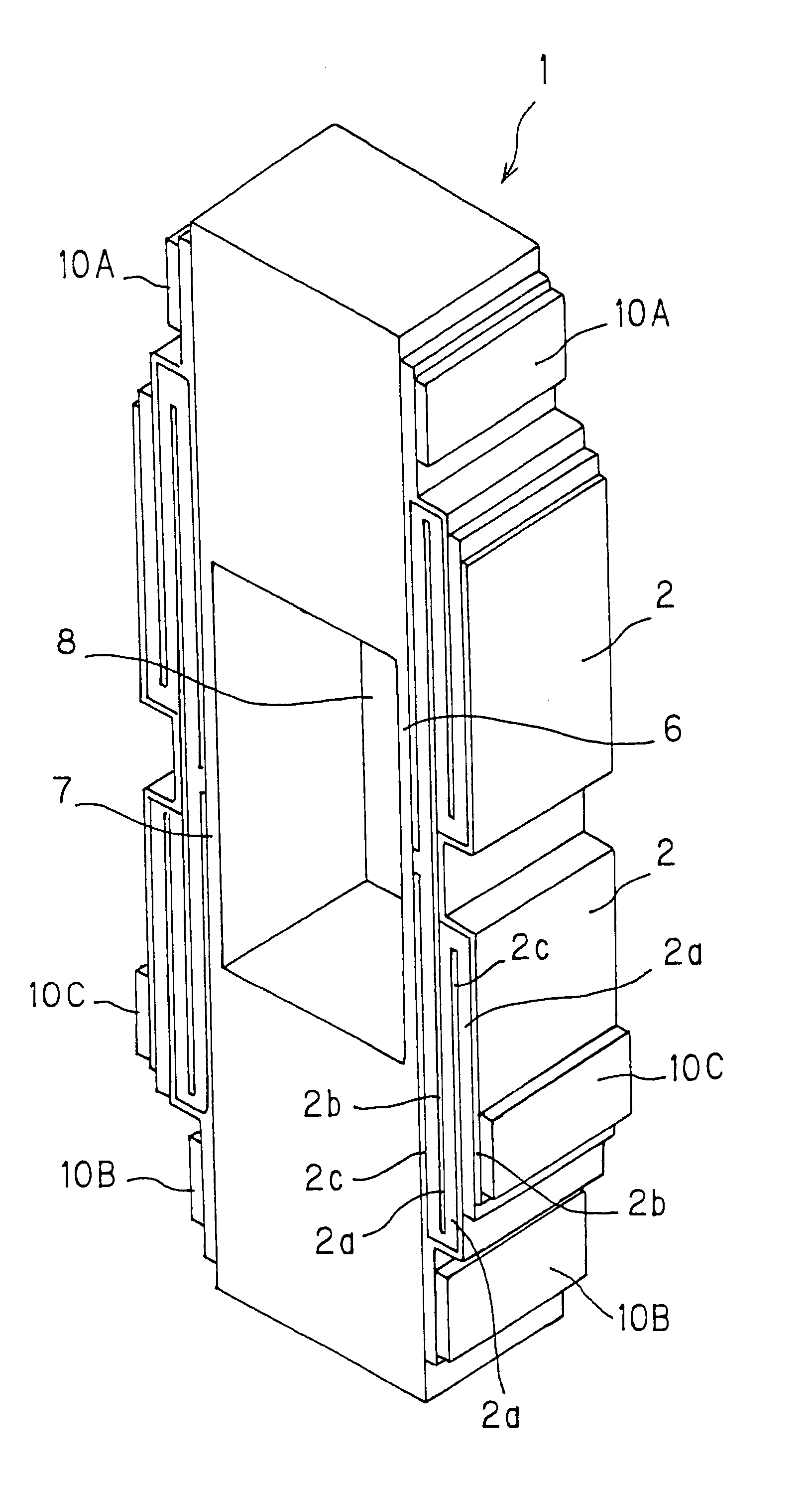
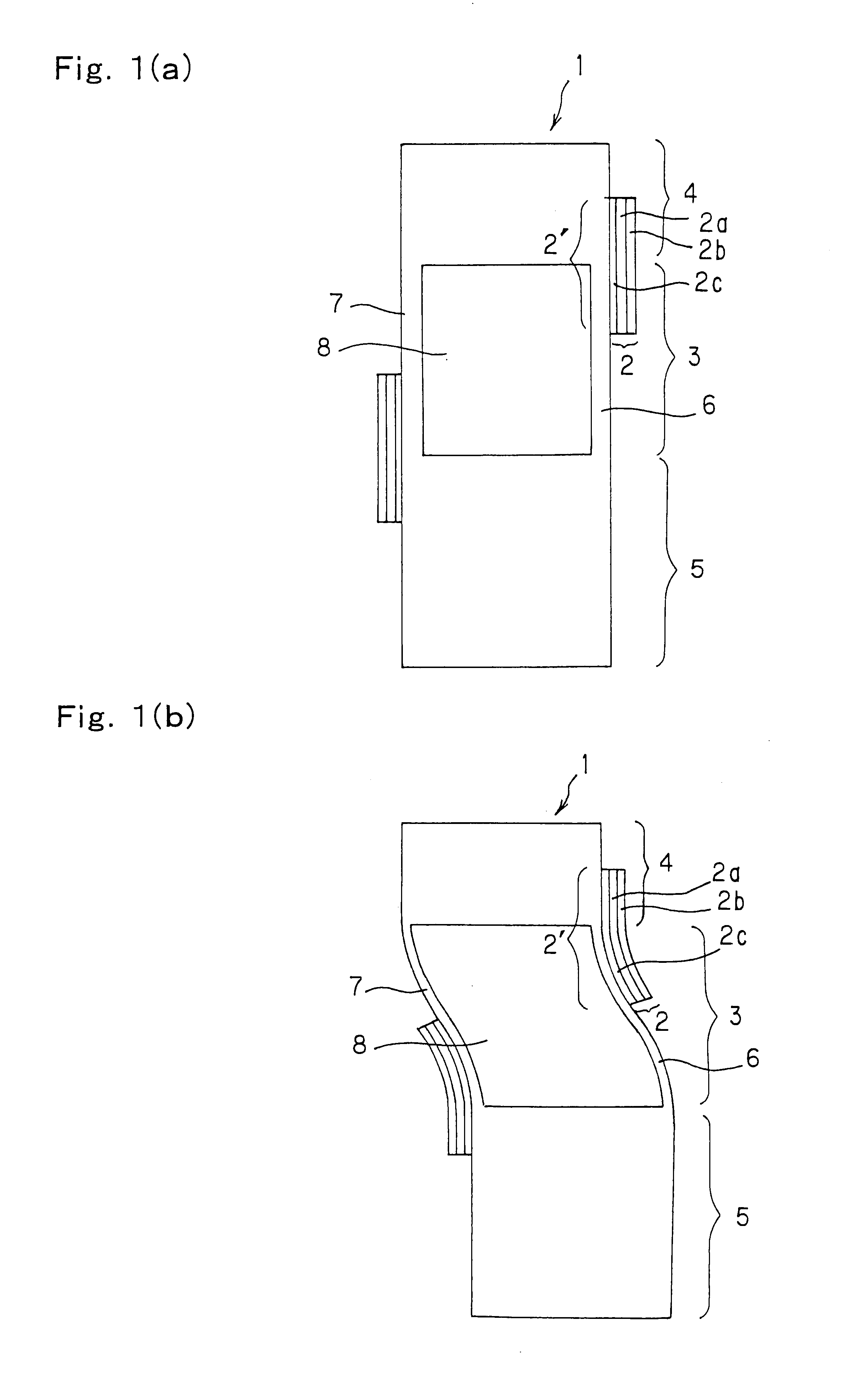
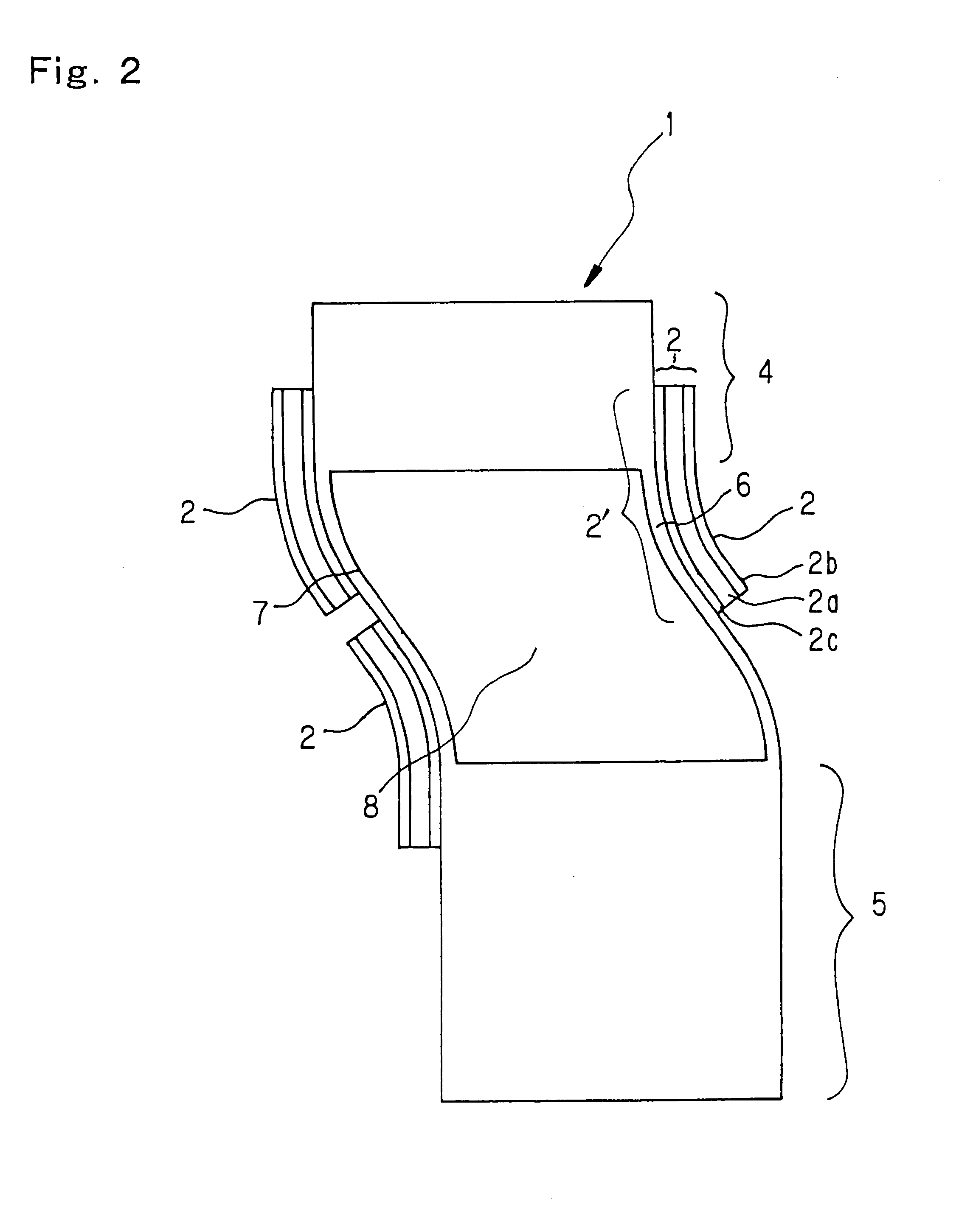
In a third embodiment, as shown in FIGS. 3(a) and (b), a device is mounted with two each, four in total, piezoelectric / electrostrictive elements respectively comprising a pair of electrodes 2b, and 2c and a piezoelectric / electrostrictive layer 2a mutually opposed on the same thin plate portions 6, and 7, and therefore four fulcrums are available for a displacement. So, if elements positioned at least in diagonal directions across a hole mutually have the same functions, driving force can be doubled by simultaneously driving the same, thus the driving force can be efficiently converted into a displacement in addition to remarkable increase in displacement quantity. Further, by forming piezoelectric / electrostrictive elements having mutually different strain direction formed on the same driving portion (thin plate portion), the displacement of the thin plate portion due to the strain such as expansion and / or contraction can be carried by respective piezoelectric / electrostrictive elemen...

example 1

LAMINATION EXAMPLE 1

After sequentially laminating a ceramic green sheet (hereinafter referred to as "GS") 1 for the thin plate, GS1 having a hole formed thereon (hereinafter referred to as "with a hole"), GS2 with a hole, GS3 with a hole, GS4 with a hole, and GS2 for the thin plate, all shown in FIG. 20, the lamination is subjected to a compression to produce an integrally laminated ceramic green body.

example 2

LAMINATION EXAMPLE 2

Step 1: After laminating GS1 for the thin plate over GS1 with a hole, the lamination is subjected to compression to produce an integrally laminated ceramic green body.

Step 2: After laminating GS4 with a hole over GS2 for the thin plate, the lamination is subjected to compression to produce an integrally laminated ceramic green body. Step 3: After sequentially laminating the integrally laminated ceramic green body obtained in step 1, GS2 with a hole, GS3 with a hole, and an integrally laminated ceramic green body obtained in step 2, the lamination is subjected to compression to produce an integrally laminated ceramic green body.


PUM


Abstract

A piezoelectric / electrostrictive device (P / E) includes driving, movable and fixing portions. One end of a first P / E element and P / E operating portion on the end are positioned on the fixing portion and an opposite end of the P / E operating portion of the first P / E element is positioned on a first thin plate portion. One end of a second P / E element and P / E operating portion on the end are positioned on the movable portion and an opposite end of the P / E operating portion of the second P / E element is positioned on a second thin plate portion. A hole formed by inner walls of the driving, movable and fixing portions has a central axis that extends in an axial direction substantially parallel to the thin plate portions and substantially perpendicular to the length direction, and the device is free of any other holes extending in any direction other than the axial direction.

Description

BACKGROUND OF THE INVENTION AND RELATED ART STATEMENTThe present invention relates to a piezoelectric / electrostrictive device comprising a movable portion being operated based on a displacement of a piezoelectric / electrostrictive element, or a piezoelectric / electrostrictive device capable of detecting a displacement of a movable portion by a piezoelectric / electrostrictive element, and more particularly relates to a piezoelectric / electrostrictive device which is superior in the mechanical strength, impact resistance, and humidity resistance and is capable of having the movable portion efficiently operated in a large magnitude.In recent years, in the fields of optics and magnetic recording, precision machining, and the like, a displacement element capable of adjusting an optical path length and position in sub-micron order has been required, and development has been progressed of the displacement element utilizing displacement due to the inverse piezoelectric effect or the electrostri...

Claims


Application Information

Patent Timeline
Patent Type & Authority Patents(United States)
IPC IPC(8): H01L41/09H01L41/24H10N30/20
CPCH01L41/27H01L41/0946H10N30/2043H10N30/05
Inventor TAKEUCHI, YUKIHISANANATAKI, TSUTOMUKOMAZAWA, MASATOKIMURA, KOJI
Owner NGK INSULATORS LTD
Why Eureka
Try Eureka