Y-shaped support structure for elevated rail-vehicle guideway

a support structure and elevated rail technology, applied in the direction of rope railways, transportation and packaging, ways, etc., can solve the problems of time and expense of manufacturing such structures, difficult prefabrication at a central manufacturing facility, and high construction and installation costs

Inactive Publication Date: 2003-06-03
SVENSSON
View PDF22 Cites 19 Cited by
  • Summary
  • Abstract
  • Description
  • Claims
  • Application Information

AI Technical Summary

Problems solved by technology

However, existing elevated railed-vehicle systems have several characteristics that preclude their acceptance throughout the world.
First, known support structures are heavy and excessively large making them expensive to construct and install.
Such structures are difficult to prefabricate at a central manufacturing facility and then transport easily to the location where they will ultimately be installed.
The time and expense of manufacturing such structures is a primary contributor to the excessive costs of elevated rail systems.
In addition, variations in weather, temperature, and environment at each individual support structure manufacturing site combined with variations associated with continuously having to move and set-up the manufacturing equipment at each site make it difficult to efficiently control the quality and consistency of each manufactured support structure.
However, in such cases, it is difficult to position known support structures for supporting the guideway so as to not interfere with at least one vehicle traffic lane below the guideway.
However, placement of known support structures adjacent to roads is often impractical for at least two reasons.
First, known support structures have wide and relatively shallow foundations.
Accordingly, they cannot be easily installed adjacent to existing roadways because these foundations would cover existing underground utilities such as sewer and electric lines.
Even in cities not having such building code restrictions, it is not desirable to cover existing underground utilities with essentially immovable foundations weighing several tons.
Second, most cities have tall buildings adjacent to its sidewalks.
Positioning known support structures on sidewalks would often position the elevated vehicle guideway too close to these buildings.
In many cases, a vehicle running on such guideway would not be able to turn without contacting a building.
Finally, known wide and shallow elevated rail support structure foundations do not provide optimal support during seismic activities, such as earthquakes.

Method used


Image

  • Y-shaped support structure for elevated rail-vehicle guideway
  • Y-shaped support structure for elevated rail-vehicle guideway
  • Y-shaped support structure for elevated rail-vehicle guideway

Examples


Embodiment Construction

In light of the variety in guideway support shapes 70a,b,c and available support structure foundations 56a,b, a variety of combinations of these elements are available to accommodate the particular support structure needs of a given project. The following descriptions provide a representative sample of the various combinations of these elements. It is not intended to be exhaustive.

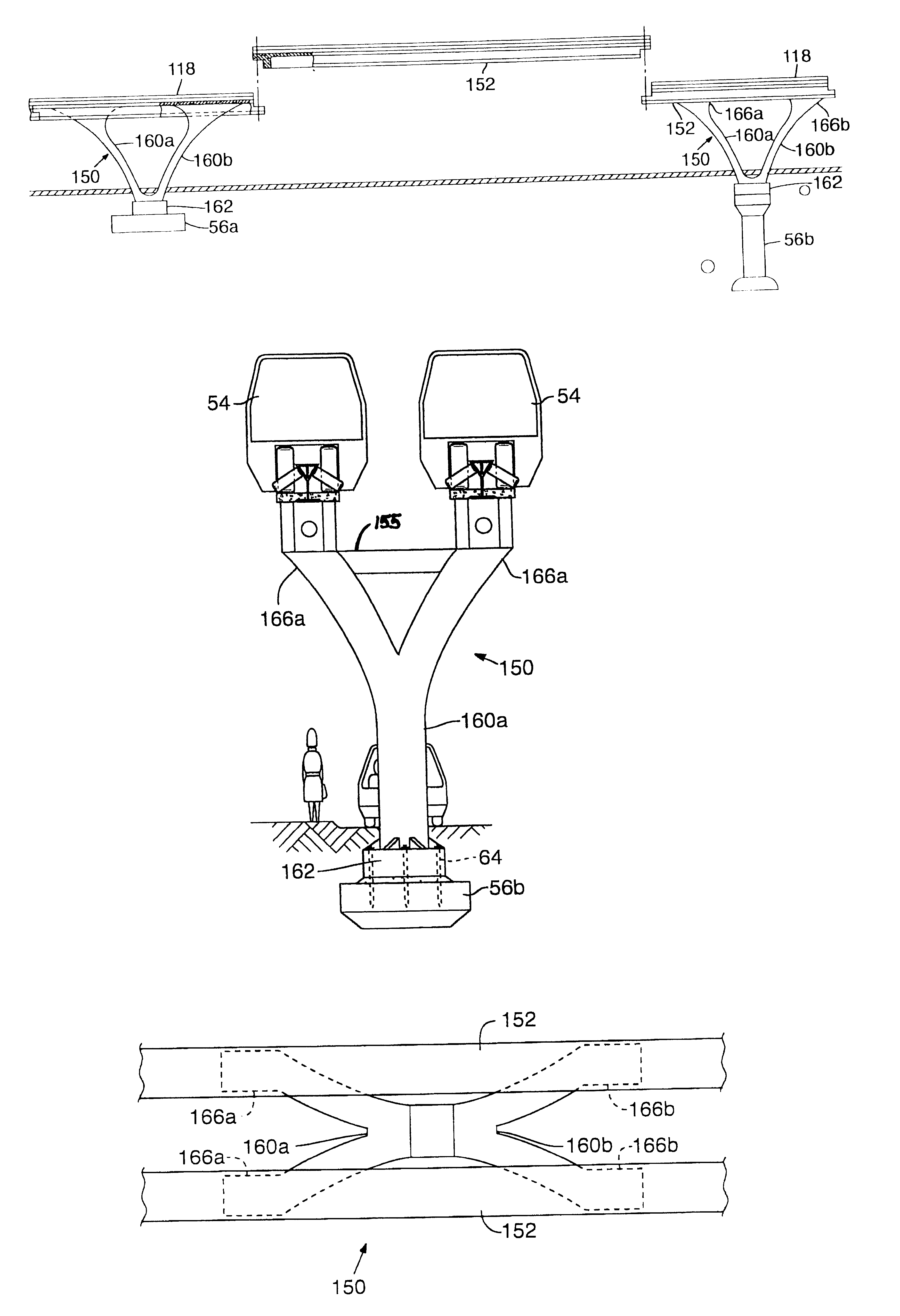
A first preferred combination of elements is shown in FIGS. 3A-3C. It features the symmetrical Y-shaped guideway support 70a supporting two guideways 52a,b. The support is secured to column 60 which rests on a traditional spread foundation 56a.

FIG. 4 shows a second preferred combination where the column 60 rests on a traditional spread foundation 56a with the offset Y-shaped guideway support 70b supporting two guideways 52a,b. A third preferred combination is shown in FIG. 5 which shows the same column 60 and foundation 56a of FIG. 4 supporting a single guideway 52a without any sort of independent guideway...


PUM


Abstract

The invention is a support structure for a railed-vehicle that includes individual, unassembled components sized for easy transport. In one embodiment, the support structure includes curved columns integrally-formed with a base, the columns imparting a curved, Y-shaped configuration to the support structure. The components may be prefabricated with known materials and methods and transported to an installation site for assembly. The support structure is preferably sized to support one or two vehicle guideways. The support structure may include a pile foundation for improved support during seismic activity and to facilitate installation on existing streets and sidewalks without covering or interfering with underground plumbing or utilities. Preferably, multiple sections of the guideway are rigidly secured together through expansion joints to define a continuous guideway such that loads on the guideway are distributed over multiple columns.

Description

1. Field of the InventionThe present invention relates to a support structure for an elevated railed-vehicle, such as a monorail. The invention concerns, more particularly, an elevated monorail support structure constructed of prefabricated components that may be easily transported to an installation site and assembled together at the installation site. The support structure preferably includes a pile foundation for improved support during seismic activity and to facilitate installation on existing streets and sidewalks without covering or interfering with underground plumbing or utilities.2. Description of Background ArtElevated railed-vehicle systems, such as monorail systems, have numerous benefits, particularly in overcrowded urban environments where the surface streets are congested with traffic and traditional forms of mass transportation, such as buses, must compete for space with existing traffic. For example, a dedicated elevated guideway vehicle system operates above city ...

Claims


Application Information

Patent Timeline
Patent Type & Authority Patents(United States)
IPC IPC(8): B61B13/04E01B25/08E01B25/10E01B25/00
CPCB61B13/04E01B25/10E01B25/08B60L2200/26E01B25/00
Inventor SVENSSON
Owner SVENSSON
Why Eureka
Try Eureka